


1. Initial response
In 2005 DreamWorks released a movie called Robots. The style of this artist’s work really reminds me of this movie. My initial thought was that it looks like a weird futuristic coffee maker right out of the movie. The piece is a little goofy and sparks a bit of joy when I look at it. Something about all the different shapes sizes and colors grabbed my eye as I was looking through all of this artist’s works. I noticed that the name of the piece is “Seated Woman” and I must say that I do not understand why it is called that. I can see some of the components that relate to this title but I will need more time to figure out how to make sense of it all.
2. Object description
Front and center is a white ceramic vase with a very skinny neck ending with a small flair at the top. Perched on top of the vase is a triangle object with a whimsical face made out of various triangles and ovals. Behind this vase sits many other objects. In the very back is a white chair with a chair back that looks like sound insulation. In the middle between the chair and the vase are two objects on the same plane. On the left is a black swirly tube that sort of resembles a small water slide. On the right side of that plane is a golden tube with a red base that sits halfway up the vase. Out of the base, the golden tube moves up and to the left, curving behind the head situated in the base.
3. Technical Decisions
This work is not a physical sculpture but it is presented in what looks like a room. If you look at the very very back of the photo you can see what looks like floor molding. This to me says the artist wanted this to look as it was photographed in a physical room. It also looks as if it was presented in a way to make each piece look supported. A lot of times it can be easy to make a digital work look as it could never exist in real life. The Constitution looks like it was planned to look as if it wasn’t planned. I find that with art that looks like it was pieced together in a random way, it actually requires a great deal of thought and practice to achieve. Since this is a digital piece, I don’t really see specific materials but rather different kinds of textures. The vase seems smooth and clean, where the gold tube behind it looks like it would feel sandblasted if you were to run your hand along with it. The context is very formal to me. The piece is presented in a room all by itself with a very clean background, drawing all the attention to it forcing you to understand that it is the art and not something to glance once at and write off immediately. The orientation is exactly like the Picasso painting that this sculpture is based on. The work is presented upfront, allowing the viewer to see it all directly.
4. The Work in the World
The most obvious relation is its connection to the Picasso piece. It is a fantastic render of Picasso’s painting in the 3-D world. The artist also added a few new details that gives it its own look and feel. It allows you to see a cleaner version of the painting. This interpretation is a good one but I think it looses a few things. For example, comparing the two, I find it easier to pick out the golden hair from the Painting, than from the sculpture. In this case, the added depth made it harder to see where the “woman” starts and ends. I think that this sculpture would look very at home in an art gallery that highlights art that is not perfect.
5. The Story It Tells
I had a really hard time finding meaning or a purpose in this work. I’ve never really understood what Picasso is all about, and since that this is a mimic of one of his paintings, it was no surprise that I would have some difficulties with this as well.
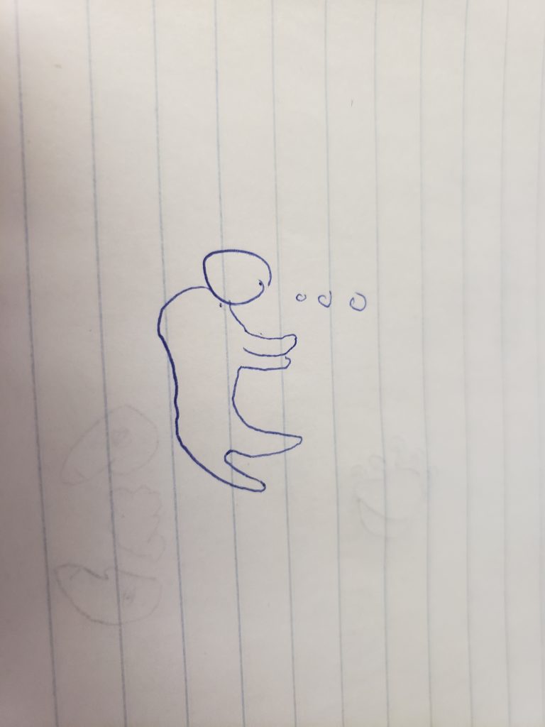
Imagine a woman sitting thinking about her life. We see a smile and happy look on her face, but yet it’s not quite right. It’s not symmetrical, it’s not what we are used to seeing. The world around her is contorted and lacks structure. The story I imagine is one of a woman who is troubled. Her life is in disarray and she sits by idly with a fake smile on her face unwilling to stand up and make a change to better her life.
[expand title=”What is Lorem Ipsum?“]Lorem Ipsum is simply dummy text of the printing and typesetting industry. Lorem Ipsum has been the industry’s standard dummy text ever since the 1500s, when an unknown printer took a galley of type and scrambled it to make a type specimen book. It has survived not only five centuries, but also the leap into electronic typesetting, remaining essentially unchanged. It was popularised in the 1960s with the release of Letraset sheets containing Lorem Ipsum passages, and more recently with desktop publishing software like Aldus PageMaker including versions of Lorem Ipsum.[/expand]
[expand title=”Why do we use it?“] It is a long established fact that a reader will be distracted by the readable content of a page when looking at its layout. The point of using Lorem Ipsum is that it has a more-or-less normal distribution of letters, as opposed to using ‘Content here, content here’, making it look like readable English. Many desktop publishing packages and web page editors now use Lorem Ipsum as their default model text, and a search for ‘lorem ipsum’ will uncover many web sites still in their infancy. Various versions have evolved over the years, sometimes by accident, sometimes on purpose (injected humour and the like).[/expand]
[expand title=”Where does it come from?“] Contrary to popular belief, Lorem Ipsum is not simply random text. It has roots in a piece of classical Latin literature from 45 BC, making it over 2000 years old. Richard McClintock, a Latin professor at Hampden-Sydney College in Virginia, looked up one of the more obscure Latin words, consectetur, from a Lorem Ipsum passage, and going through the cites of the word in classical literature, discovered the undoubtable source. Lorem Ipsum comes from sections 1.10.32 and 1.10.33 of “de Finibus Bonorum et Malorum” (The Extremes of Good and Evil) by Cicero, written in 45 BC. This book is a treatise on the theory of ethics, very popular during the Renaissance. The first line of Lorem Ipsum, “Lorem ipsum dolor sit amet..”, comes from a line in section 1.10.32.[/expand]
Process for using the Slicer app to lasercut a cardboard polyhedron
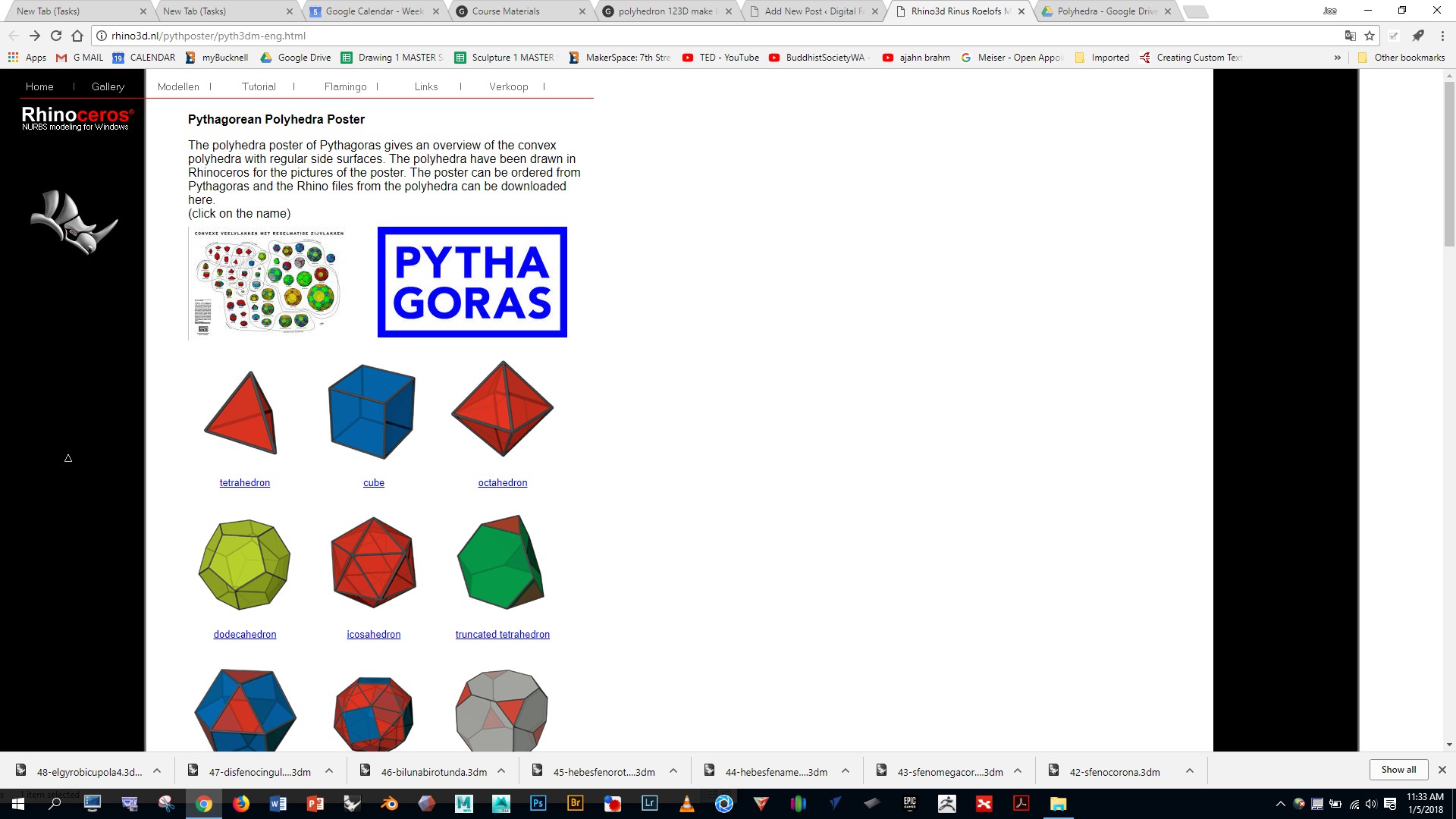
Go to http://rhino3d.nl/pythposter/pyth3dm-eng.html Choose and download a polyhedron. (Note: these polyhedra are also available here on Google Drive)
Open Rhino using a “small objects – millimeters” template, and import the polyhedron you’ve downloaded
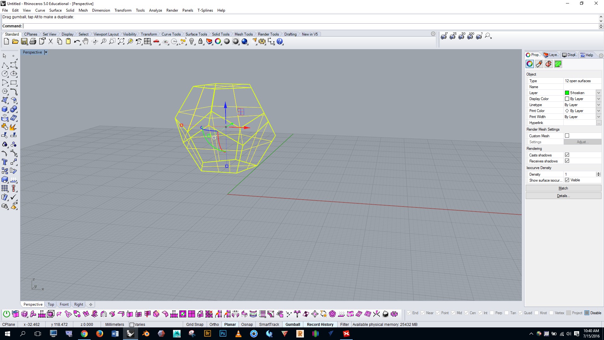
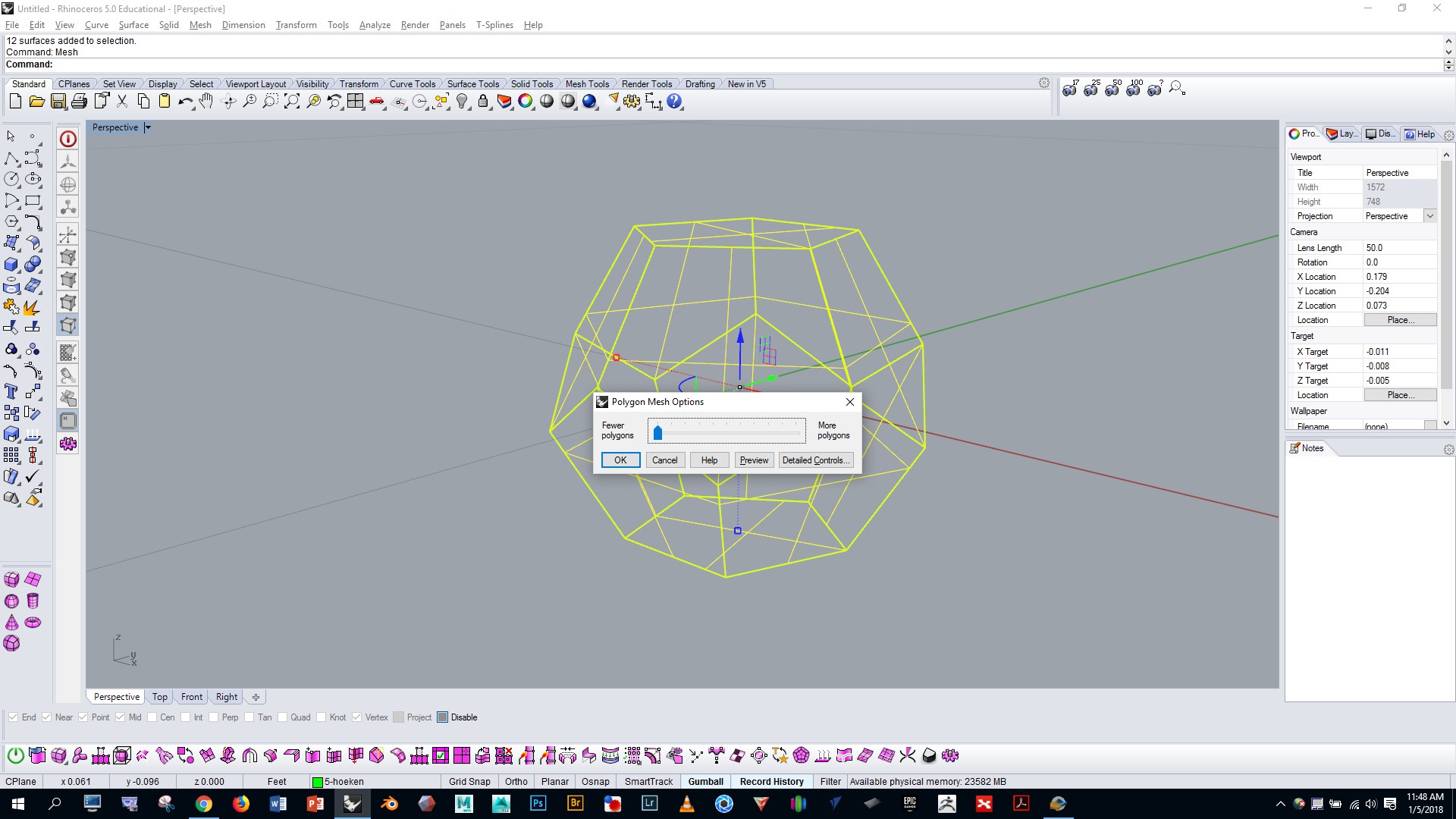
Select your polyhedron and run the “mesh” command with simple controls. Drag the slider all the way to the left.
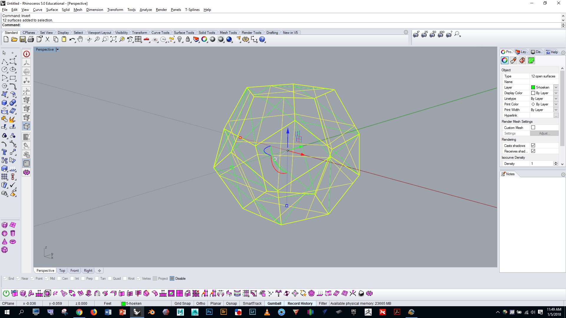
Run the “selmesh” command to select the mesh you just generated. Run the “invert” command and press the delete key. This will get rid of the original NURBS form that you imported.
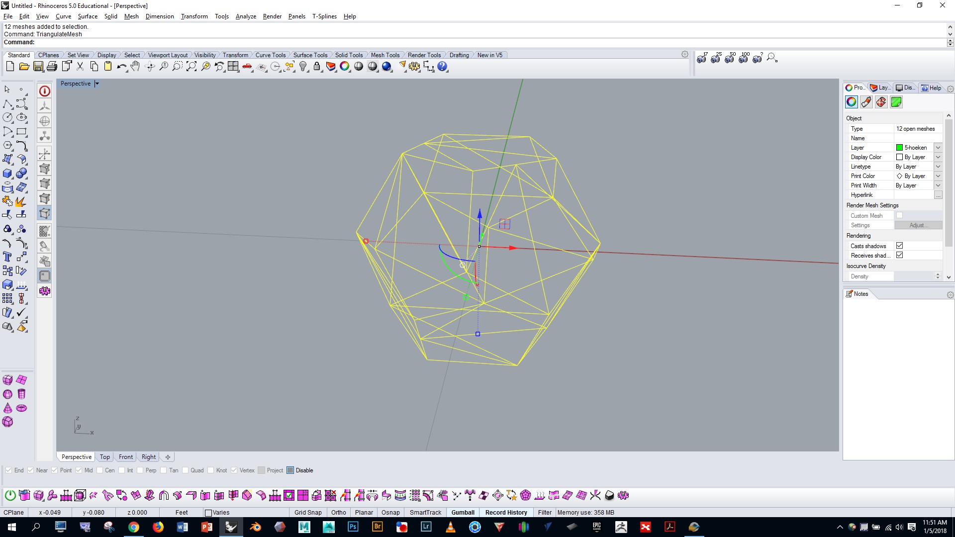
Now select the mesh and run the “triangulatemesh” command. This will ensure that your polyhedron mesh will import properly to the next program.
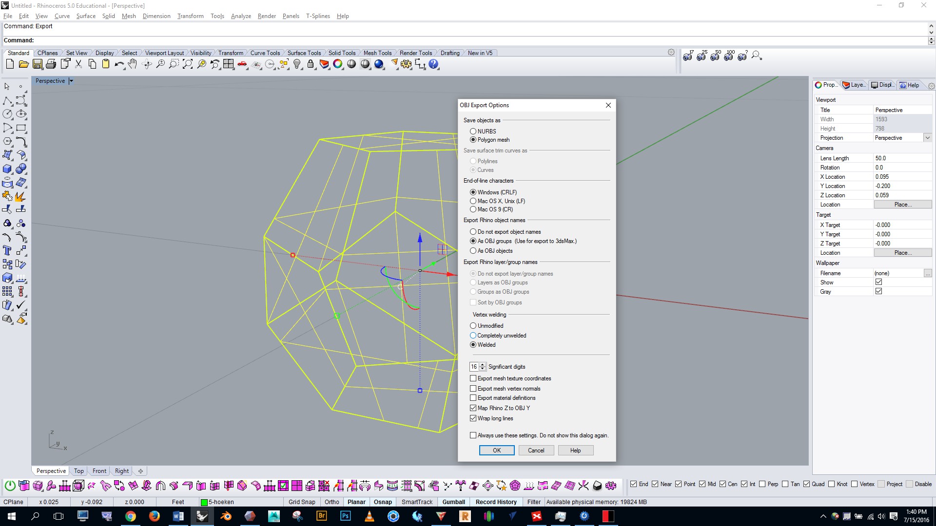
Export the polyhedron as an OBJ with the settings shown
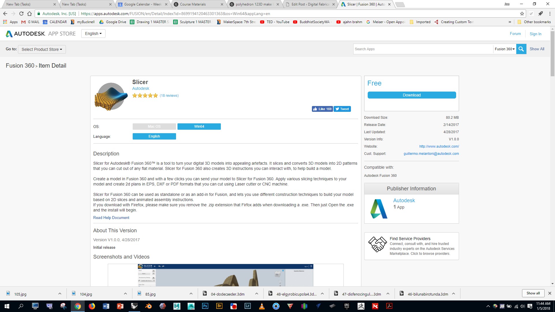
Download, install, and open the Autodesk Slicer App on your computer by following this link: https://apps.autodesk.com/FUSION/en/Detail/Index?id=8699194120463301363&os=Win64&appLang=en
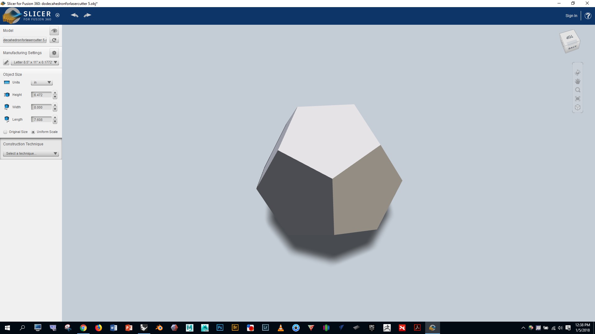
Import your OBJ file
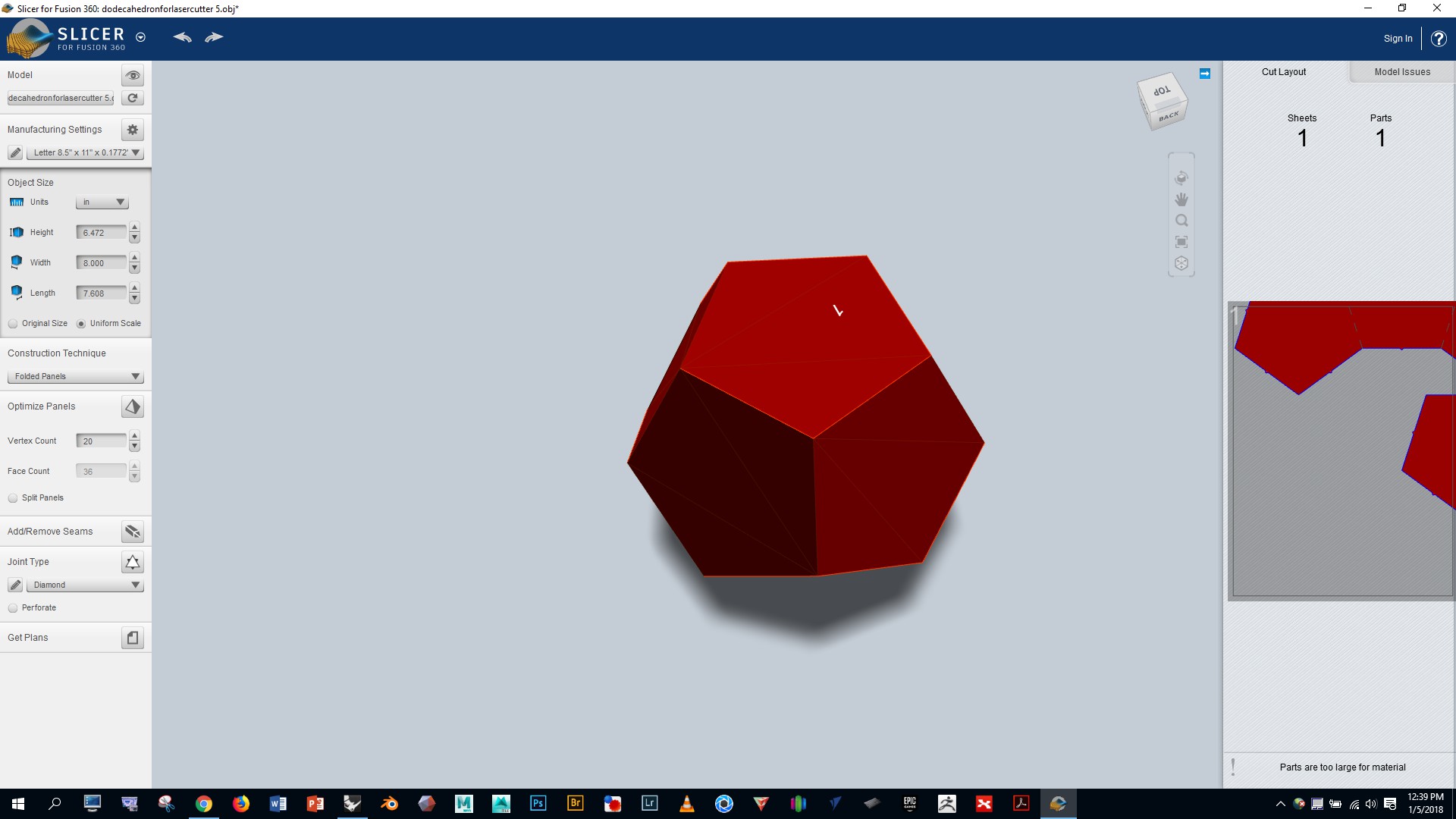
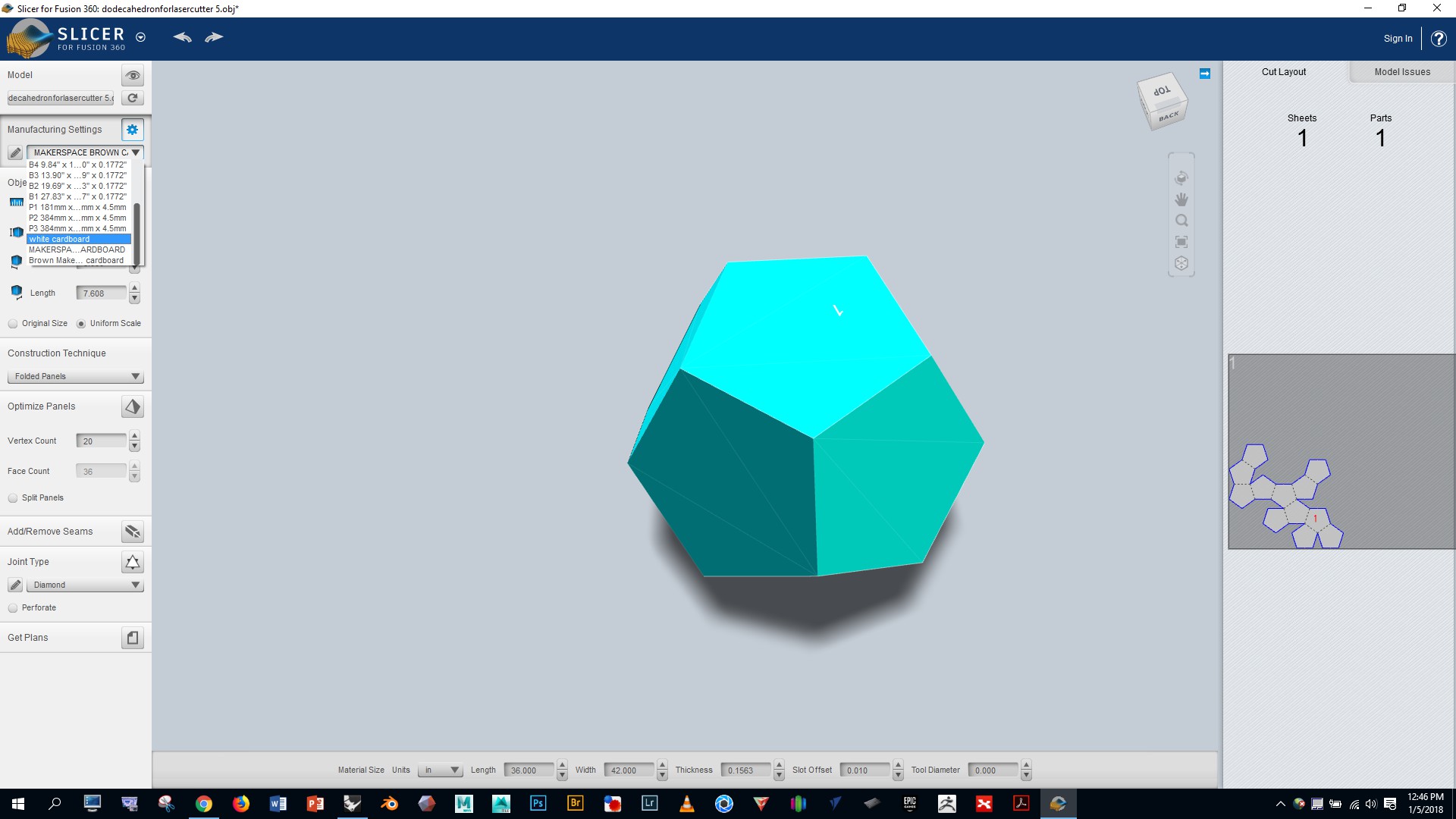
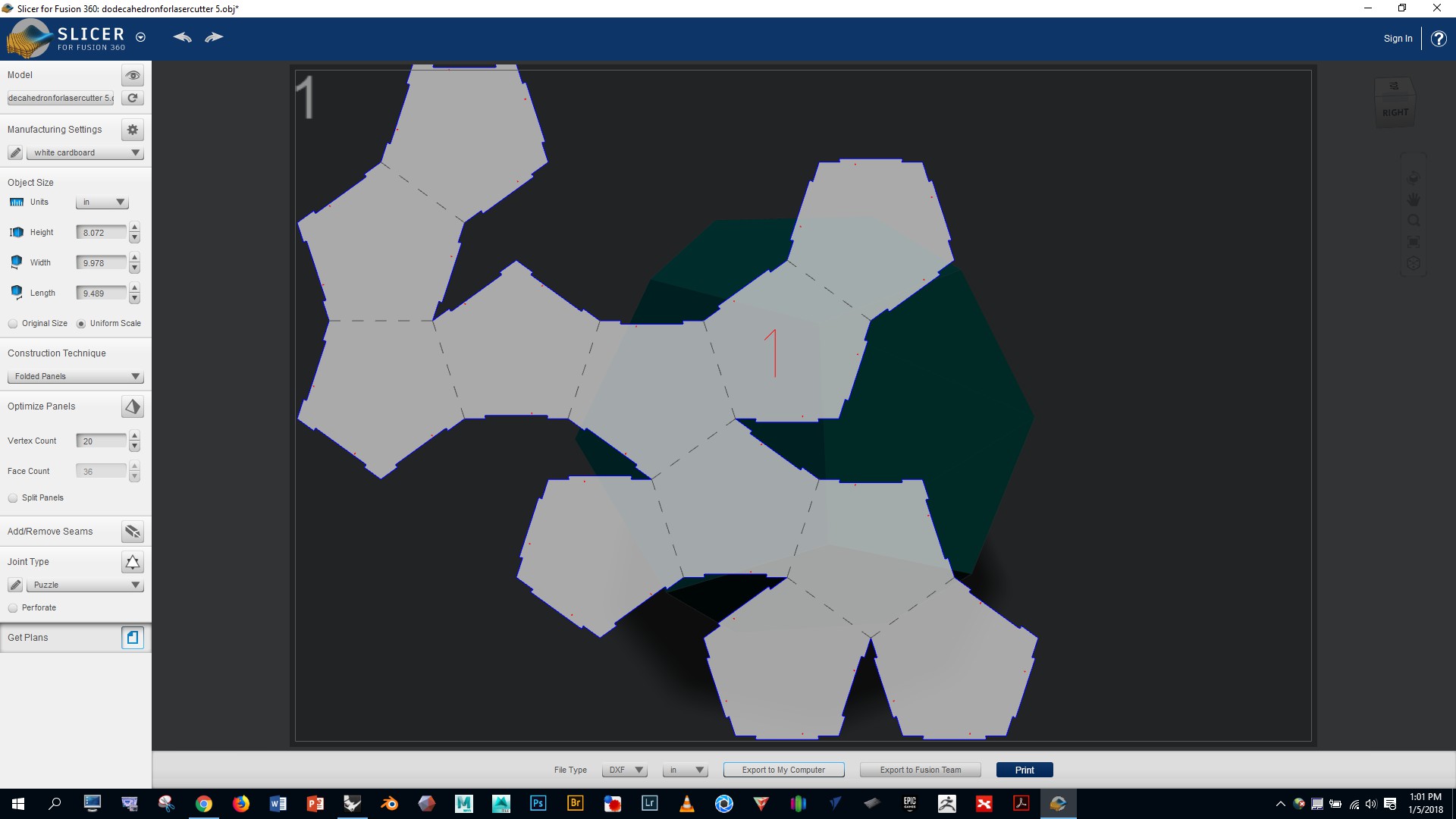
Select “folded panels” from the dropdown option on the left and notice that the program automatically generates a cut pattern for us which we can see on the far right
We’ll be working with the thin white cardboard that’s available in the Mooney Lab. Let’s configure Slicer to work with the dimensions of this material by doing the following:
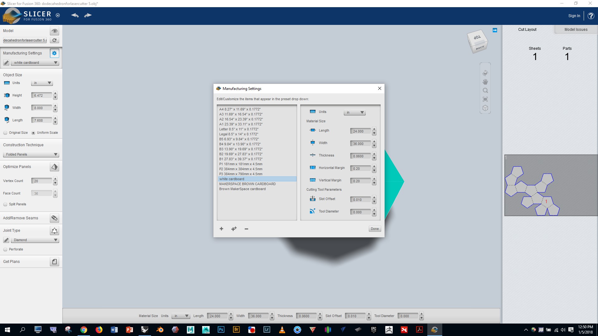
Click the little dropdown arrow on in the manufacturing settings window and select the “white cardboard” option we just created
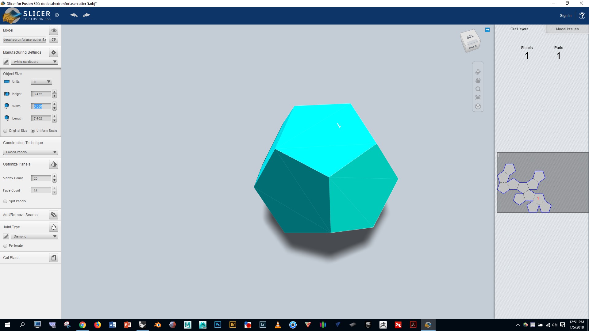
Notice on the right that our polyhedron is quite small relative to the sheet of cardboard. Adjust the values in the “object size” box to make the polyhedron larger on the cardboard
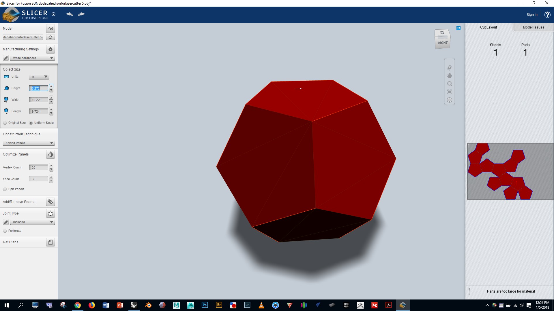
Notice that setting the object size too large will turn the whole polyhedron red, indicating that the whole pattern won’t fit on the single sheet of cardboard. Adjust as needed to make it fit on the cardboard and turn it blue.
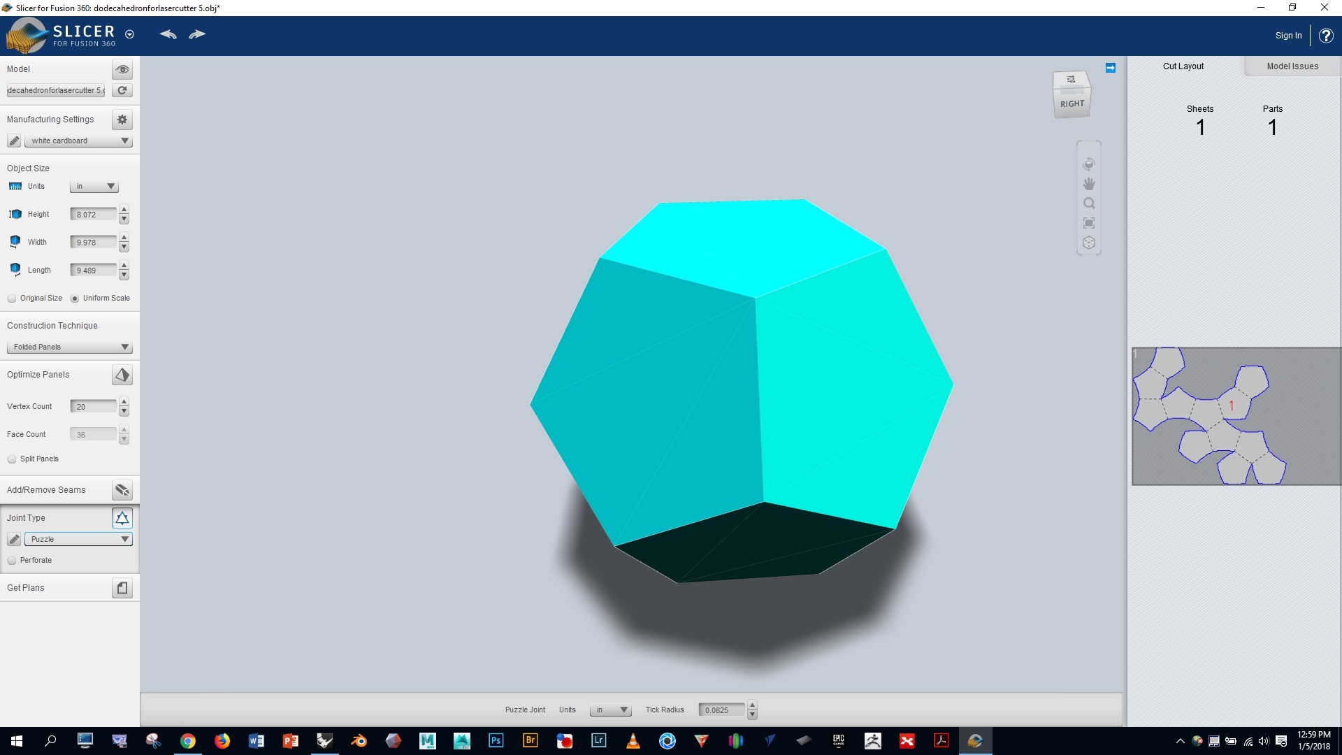
If you’d like to improve upon the automatic fold pattern generated by Slicer to make assembly simpler and/or make better use of the cardboard, click on the little razor icon in the lower left, and follow the instructions.

I used “puzzle” for the joint type, and found that it worked well for assembly
Click the “get plans” button at the bottom and export your project as a DXF file
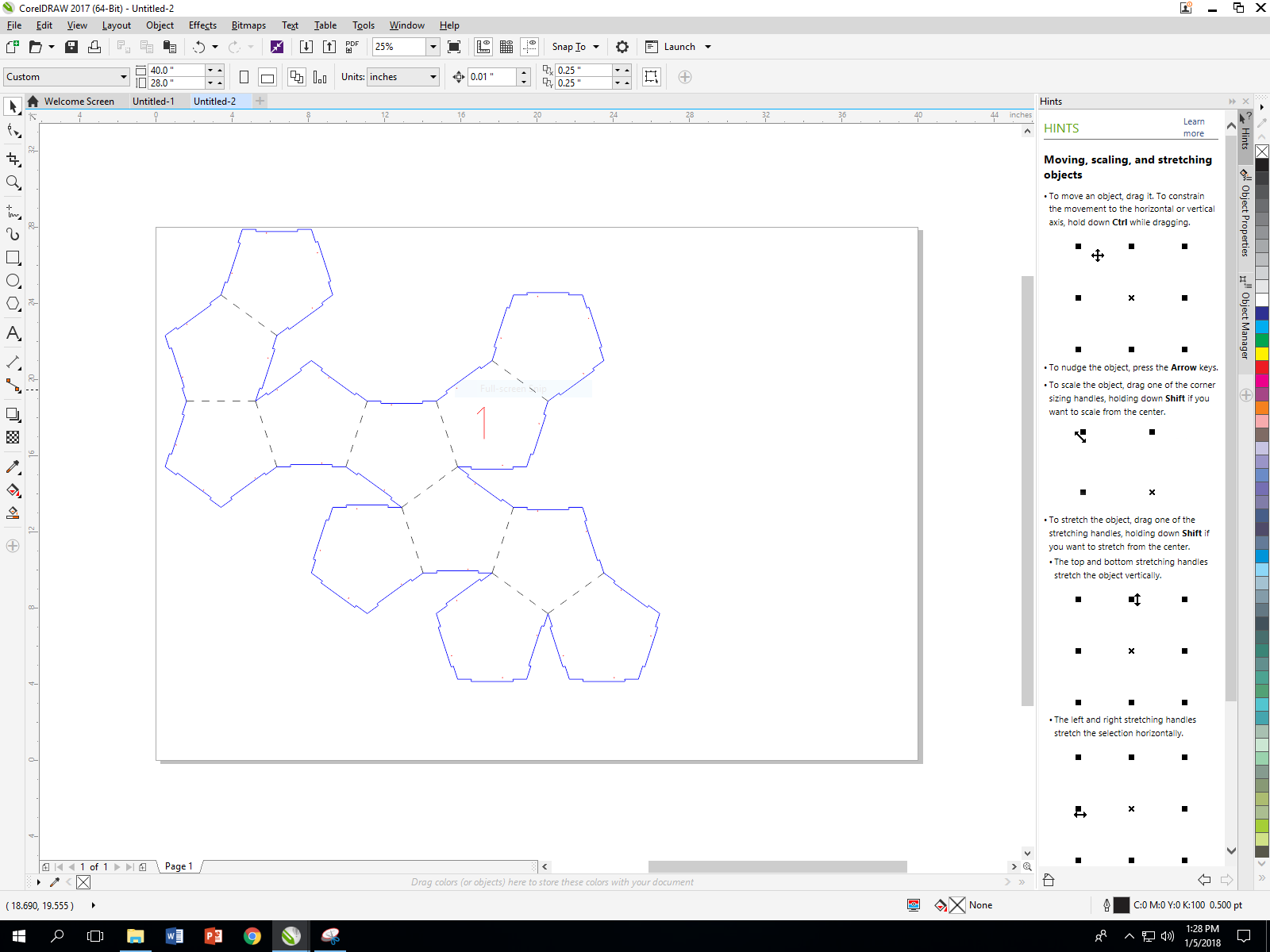
In the Mooney Lab, log on to the computer by the lasercutter and open Corel Draw (you can skip the info request screen)

Click on “file”, then “new”, and enter a width of 40″ and height of 28″. Now go to “file” > “import”, and select your DXF file with the settings shown below, and press OK
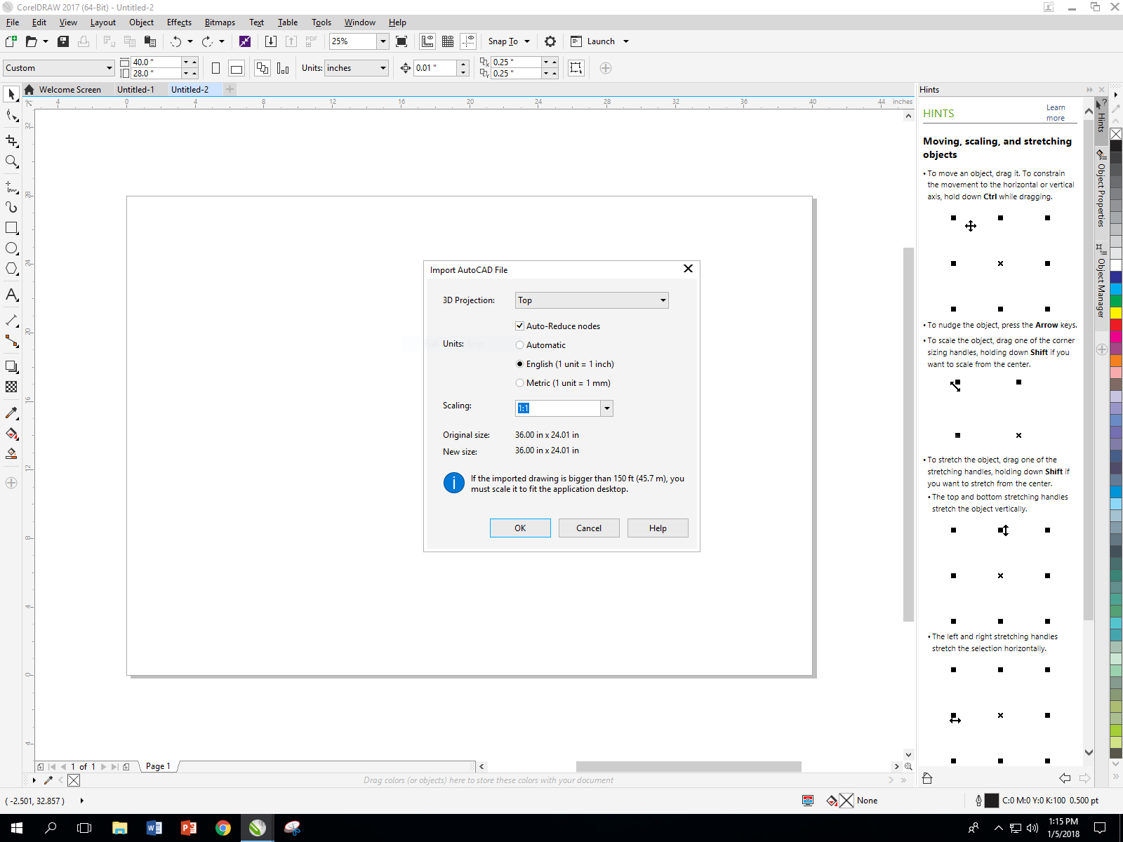
You’ll be prompted to draw the location and size of your object. We want to keep the size the same as it was in Slicer, so click the spacebar to use original position.
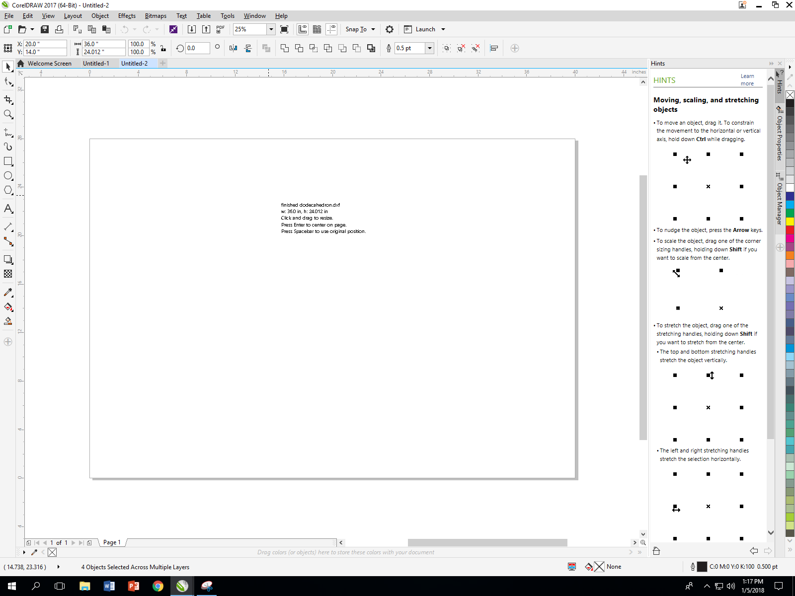
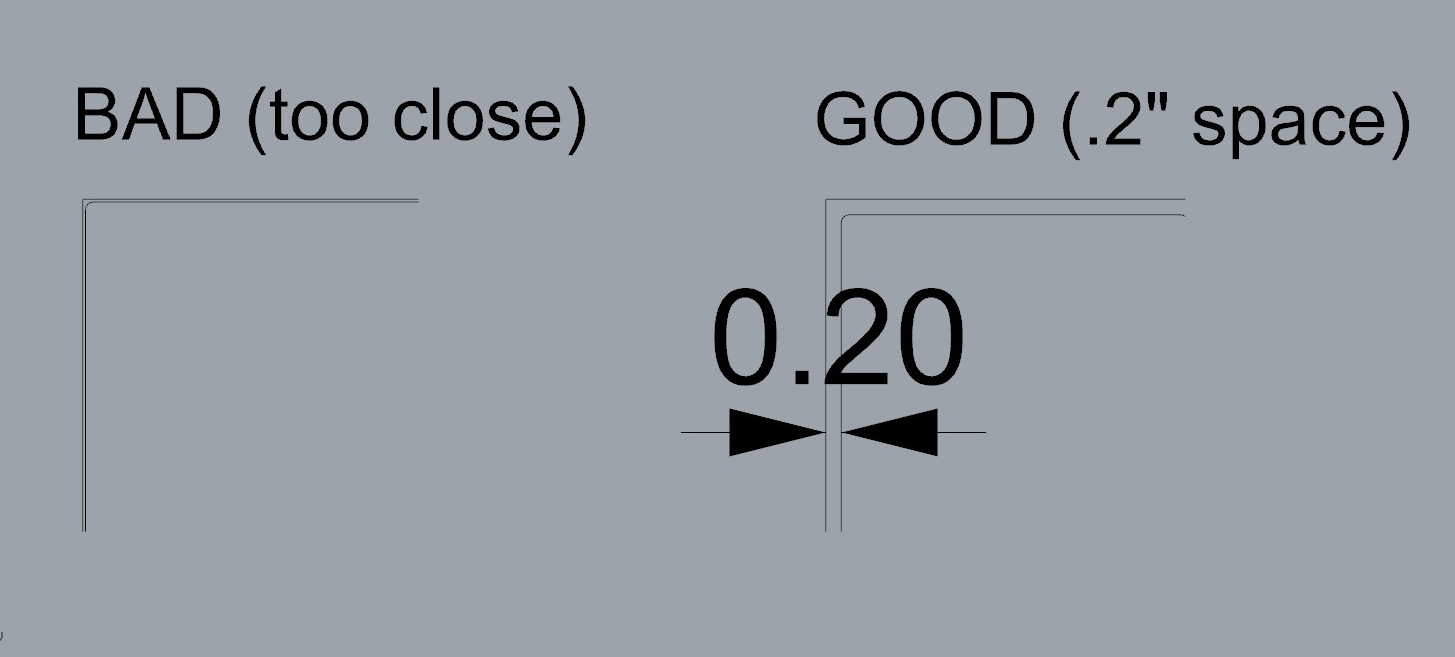
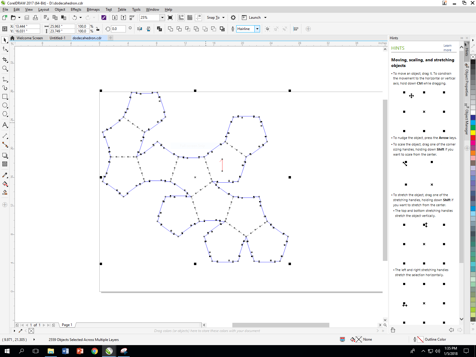
Move your design into the top left corner by adjusting the X and Y object position numbers in the top left of the screen. Your design must be within the bounds of the material by at least 0.2 inches. Otherwise, the laser could hit the rulers in the bed of the machine. Look at the images below to understand what this means more clearly.
We don’t need the rectangular border lines, so let’s select and delete them
Draw a lasso selection around all of your lines and then set the cutting width to “hairline” in the dropdown menu at the top. Making this selection is important because it will cause your lines to be vector cut rather than rastered.
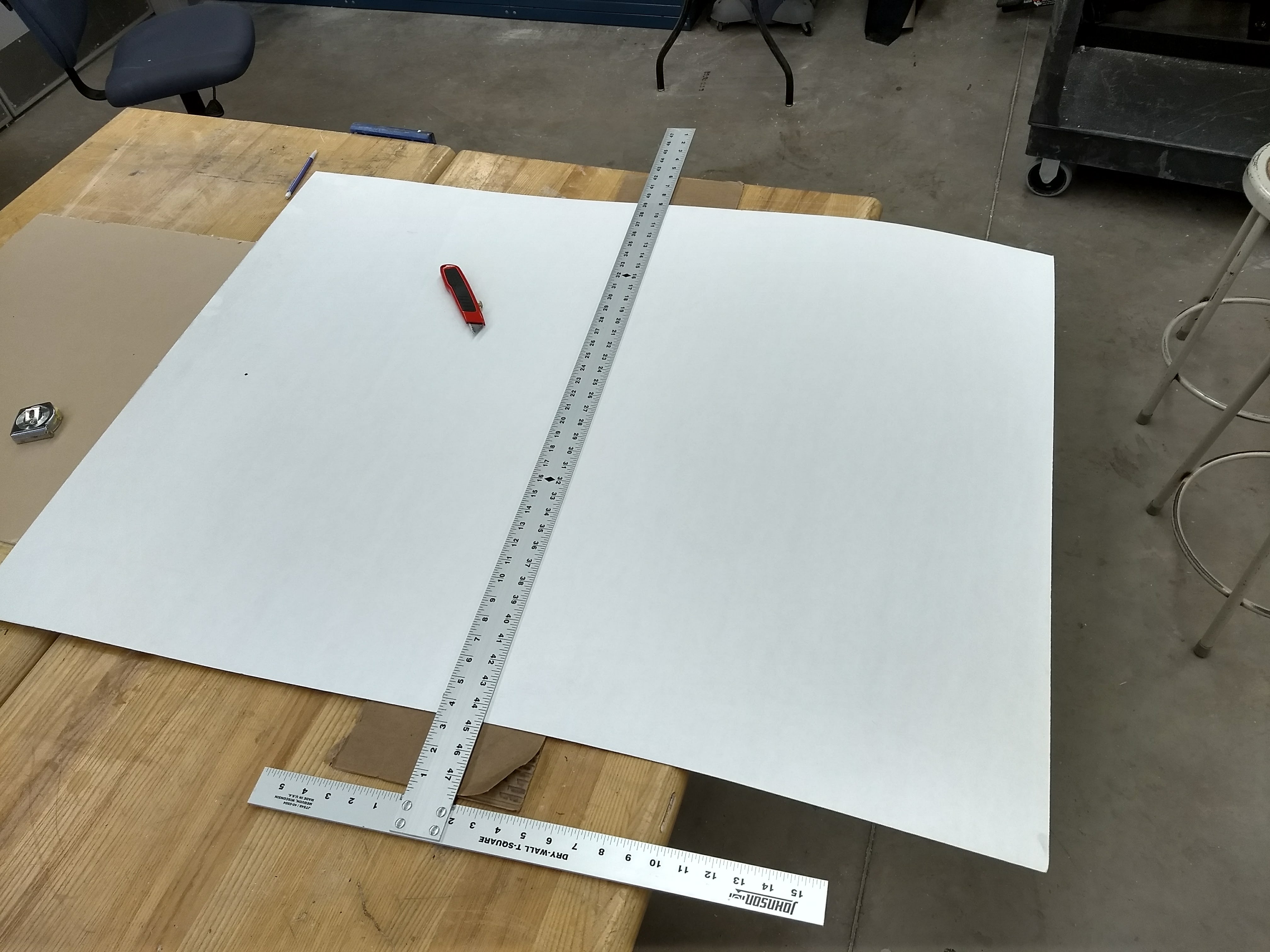
Now we’re pretty much ready to use the lasercutter. But we will first need to cut our cardboard down. Our full sheets of the white cardboard are 36″x48″, and we want to cut the sheet in half to match our drawing at 36 x 24″. Measure and cut carefully using the tools in the Mooney Lab.
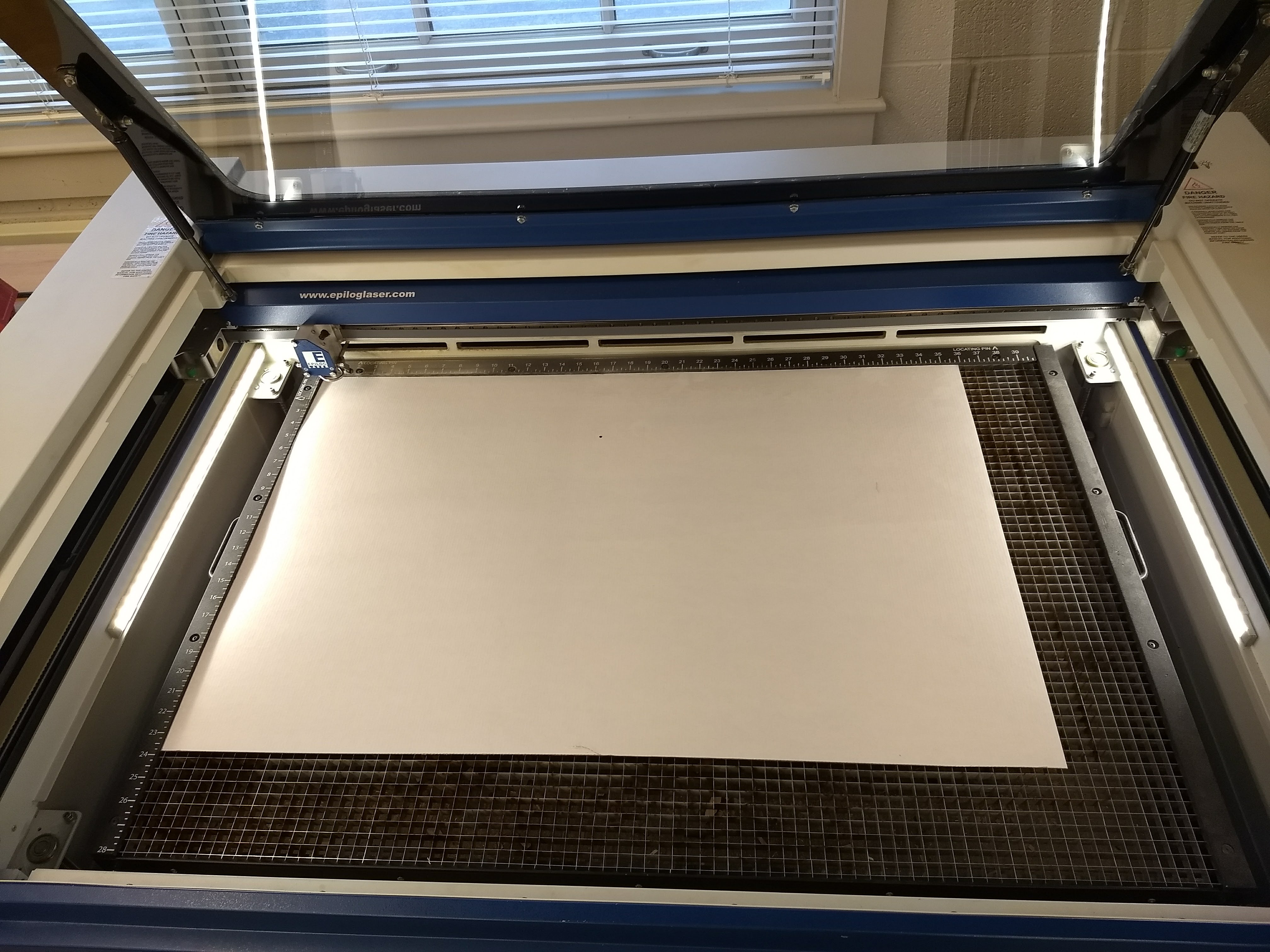
Now have the Mooney technician help you cut your design with the lasercutter. The following settings should work well for the material we’re using:
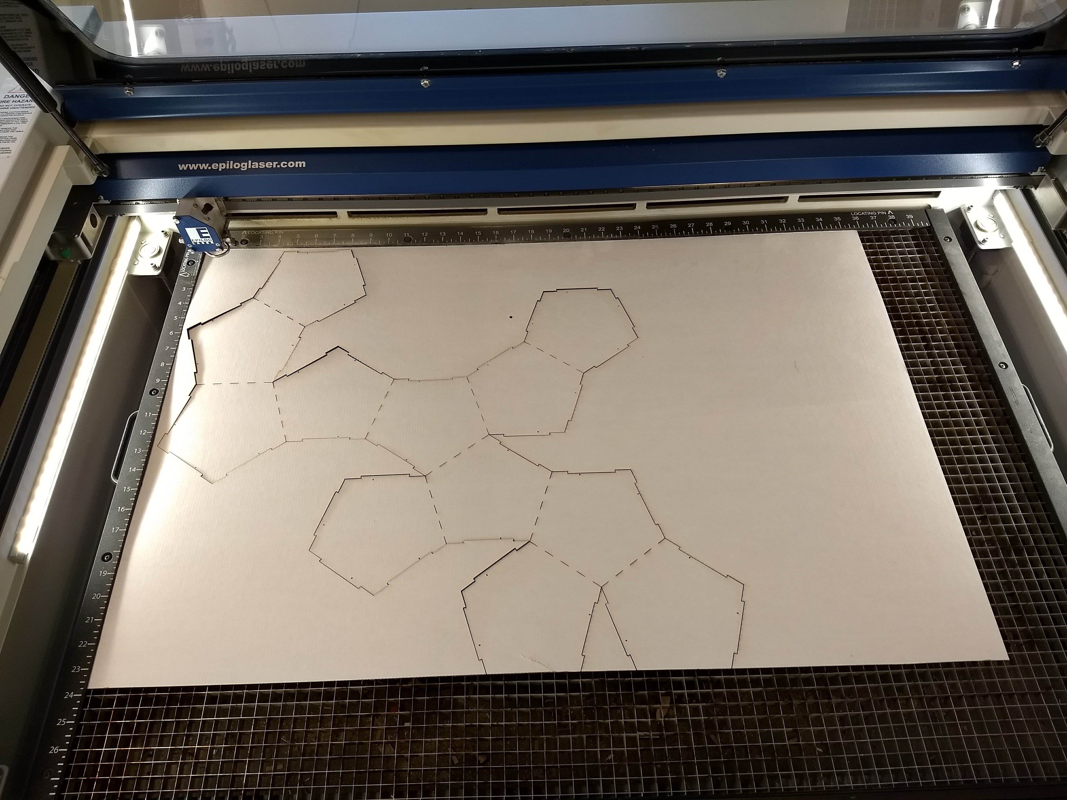
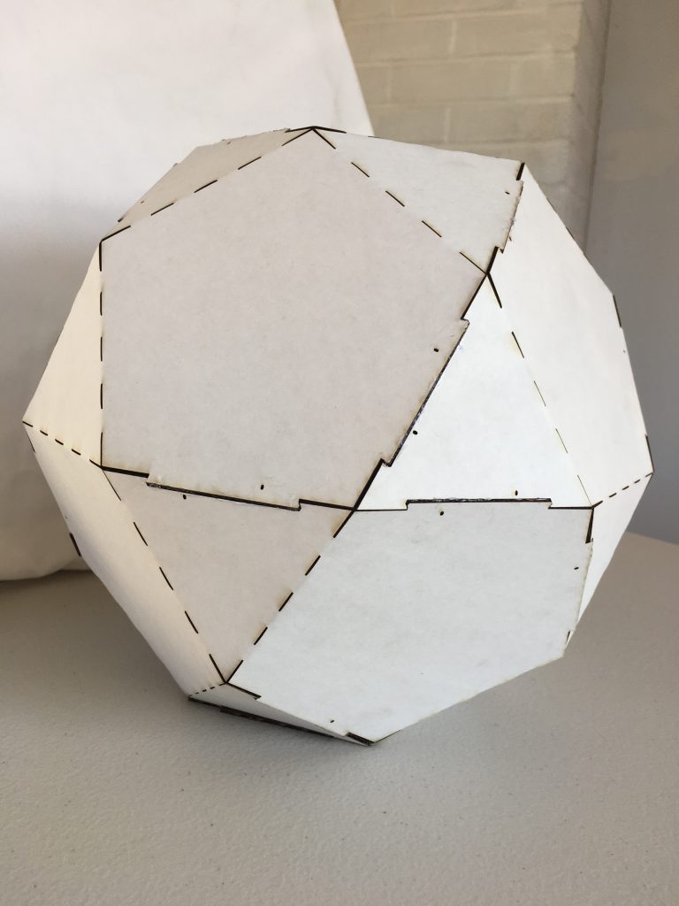
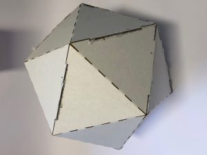
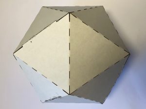
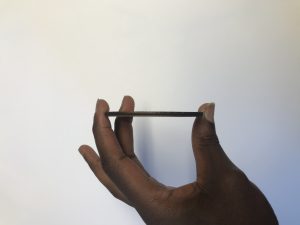
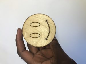
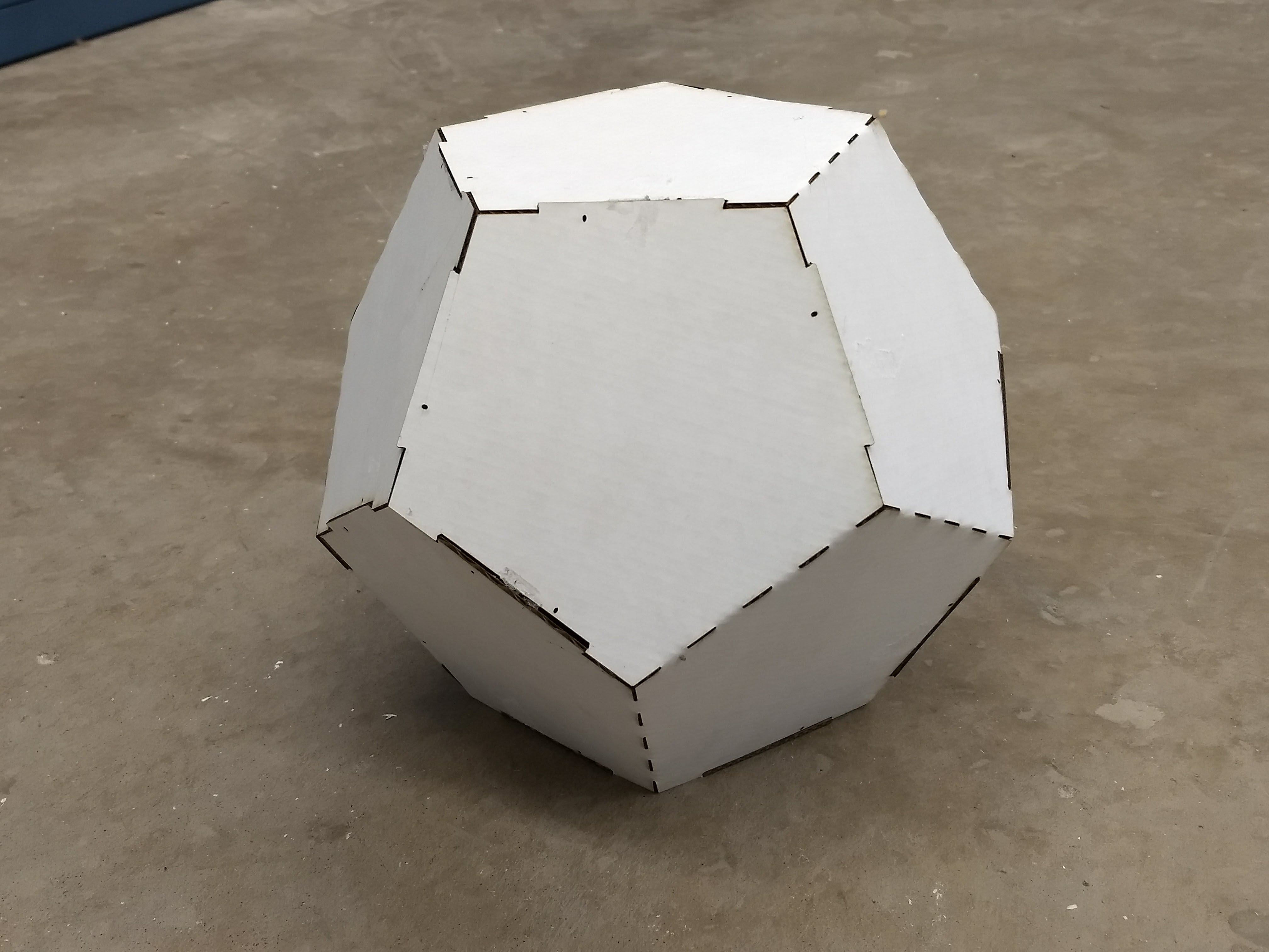
Once your pattern is cut out, after a bit of folding and some hot glue your finished polyhedron will look like this:
First, watch this video:
A FEW NOTES ON BASE MESHES
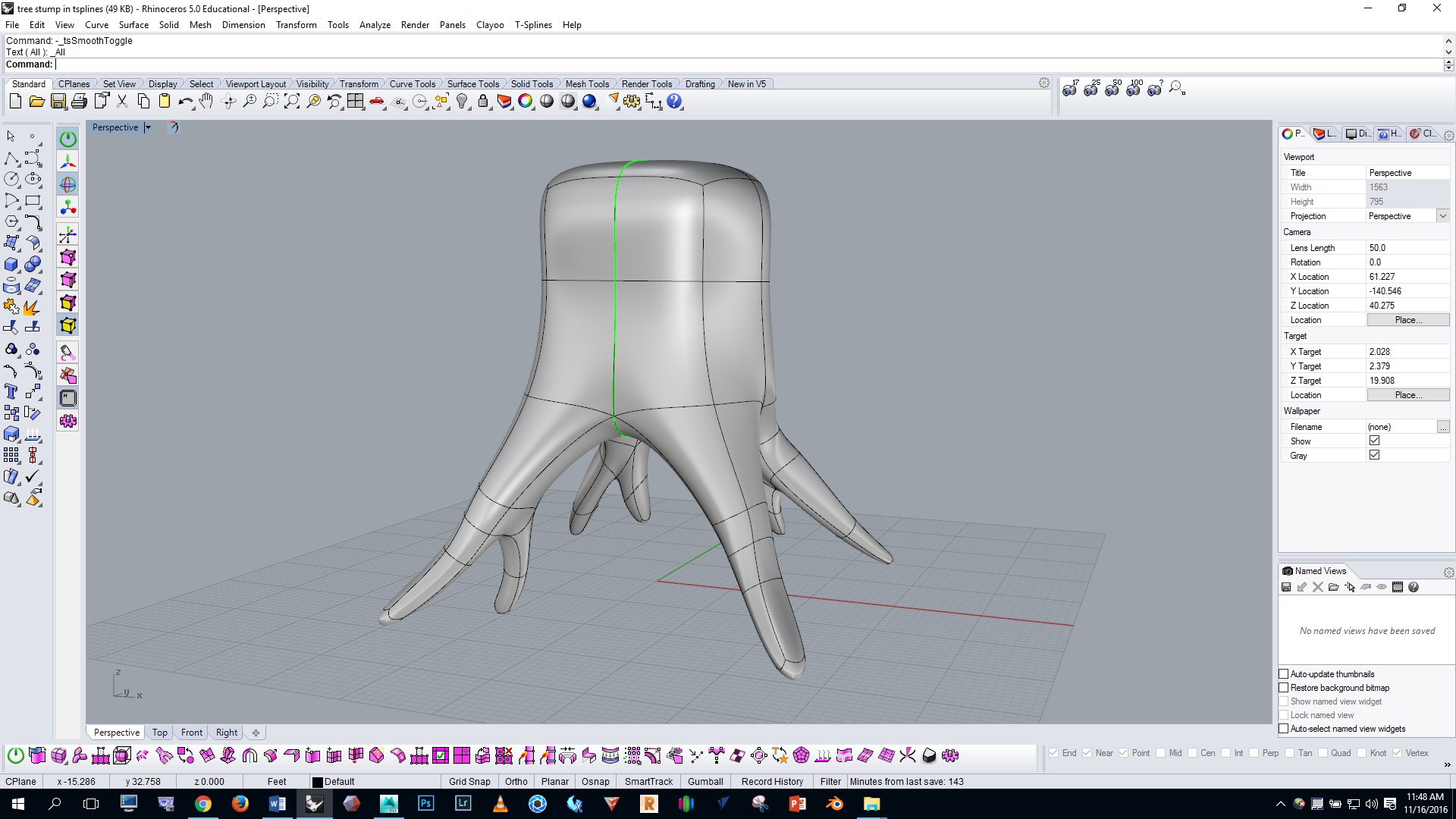
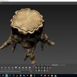
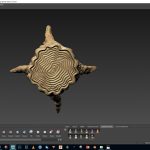
In CAD, a “base mesh” is a simple, low poly mesh that we use as a starting point for CAD sculpting. In this exercise you’ll use the base mesh of a tree stump that’s shown below as your base mesh, and you’ll detail it in Mudbox. Notice that the base mesh shown below is composed entirely of “quad” faces (four-sided polygons)—quads are important for efficient subdivision in Mudbox. We must avoid three-sided, five-sided, six-sided, etc. faces when working with subdivisions in Mudbox.
IN MUDBOX
Download the Professor’s base mesh of the stump by clicking here.
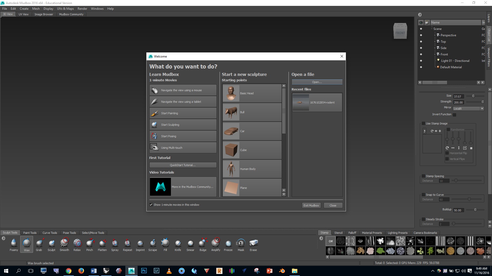
Open Mudbox, click the “open” button, and select the OBJ file for the base mesh.
Hold the space bar and notice that a menu pops up. Click on the top button. Notice that you can turn the grid and wireframe on and off.
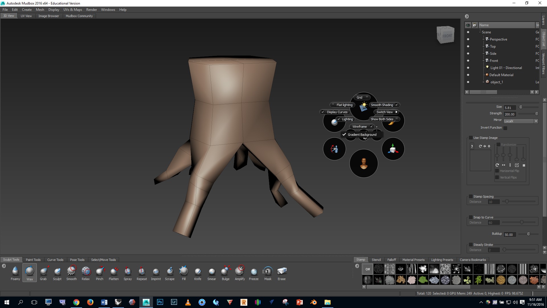
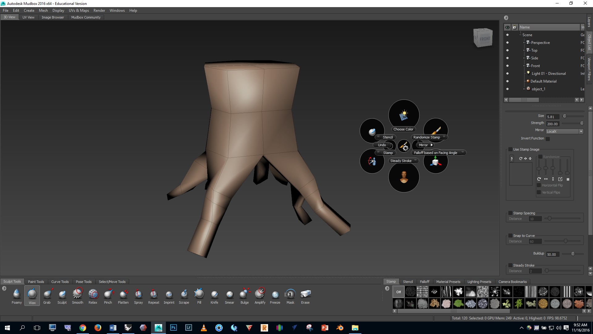
Hold the space bar again and click on the center button, then click on “mirror”, then make sure that “local x” mirroring is ON.
Viewport navigation in Mudbox:
Press SHIFT D a few times and notice in the top right corner that we’ve added a few levels of subdivision which smooths the base mesh. Now by clicking PAGE UP or PAGE DOWN we can increase or decrease the level of subdivision. If we want to make big adjustments to the geometry we should work on a low level. If we want to add fine details we work on high level.

Notice in the bottom left that we have a number of brushes to choose from. Click on the GRAB brush and then mouse over the model.
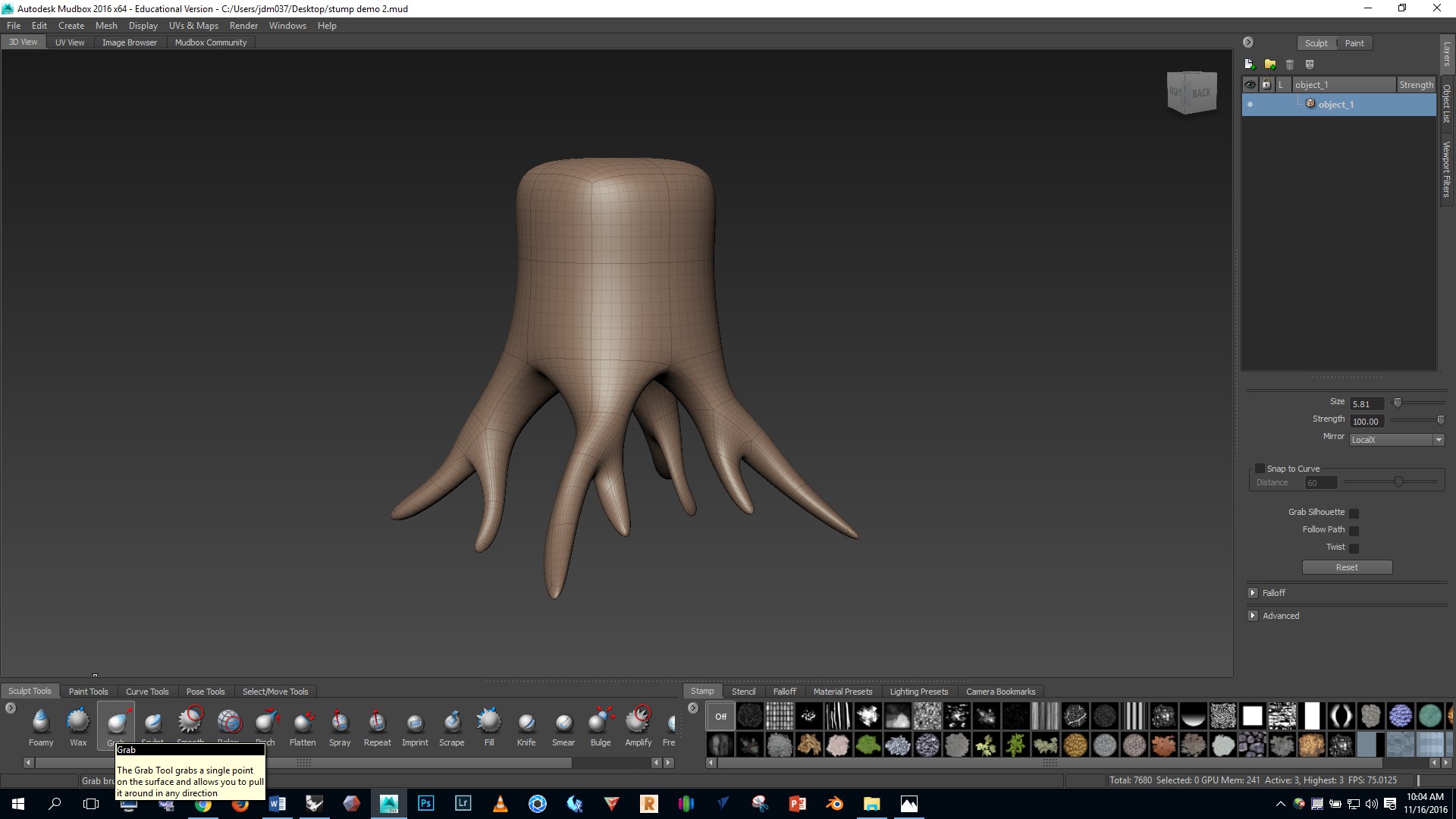
We can change the SIZE of the brush by holding B and dragging the left mouse button UP or DOWN — We can change the STRENGTH of the brush by holding M and dragging the left mouse button UP or DOWN
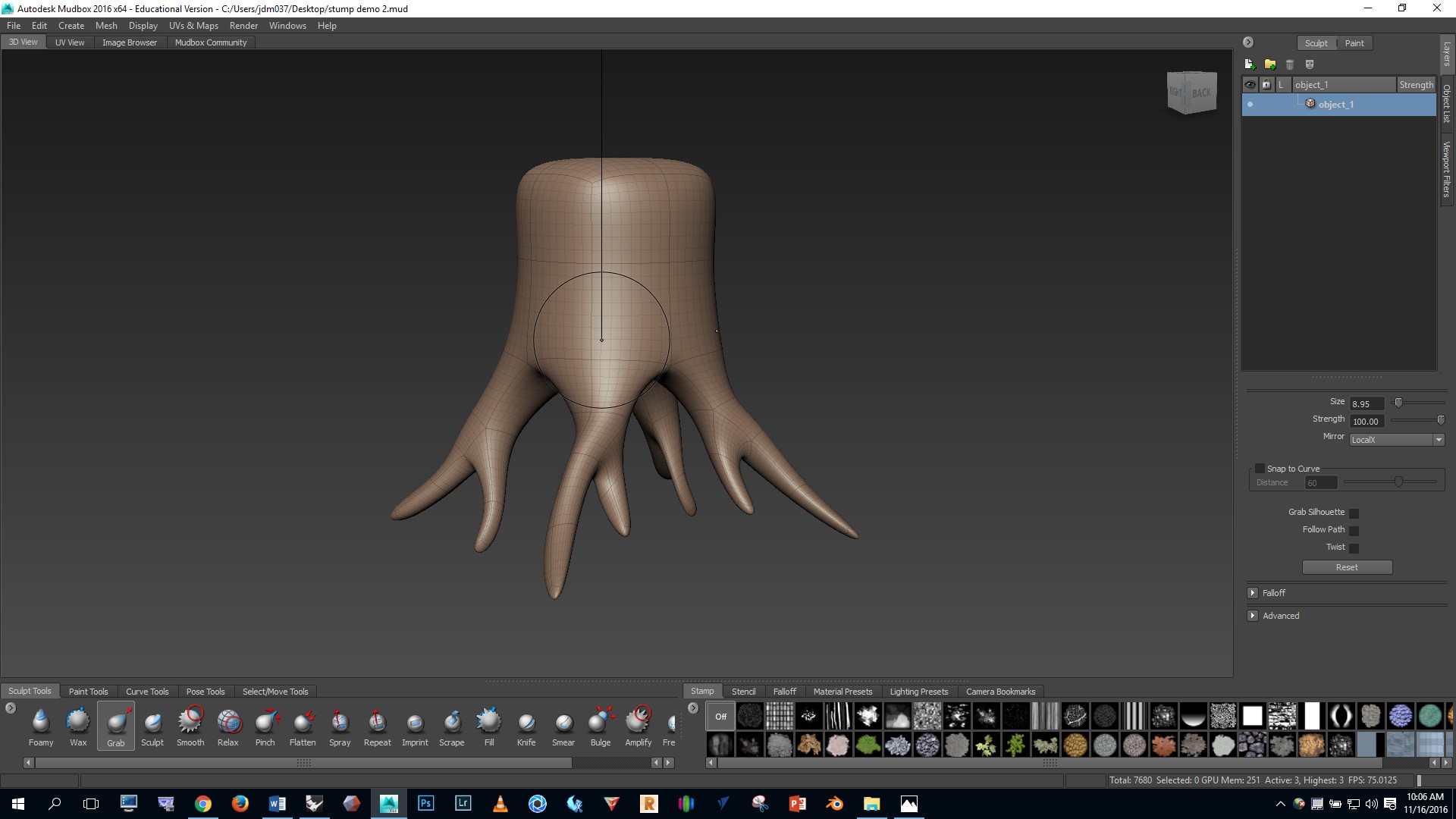
Let’s refer to these visual references as we add detail:


Use the GRAB brush to make big adjustments to the form of the roots and trunk.

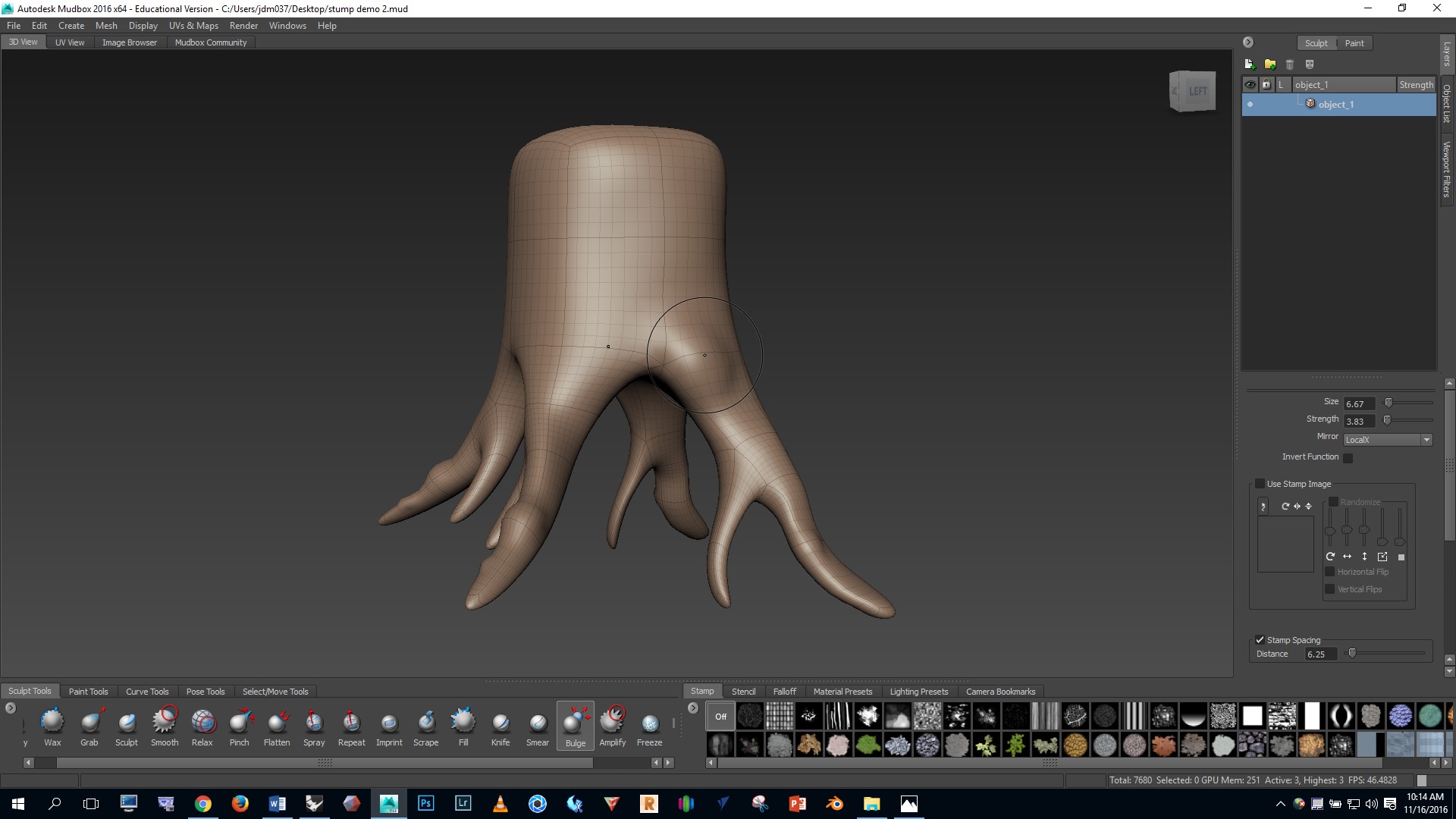
Select the BULGE brush and use it to make lumps in the roots and bulged areas on the trunk.
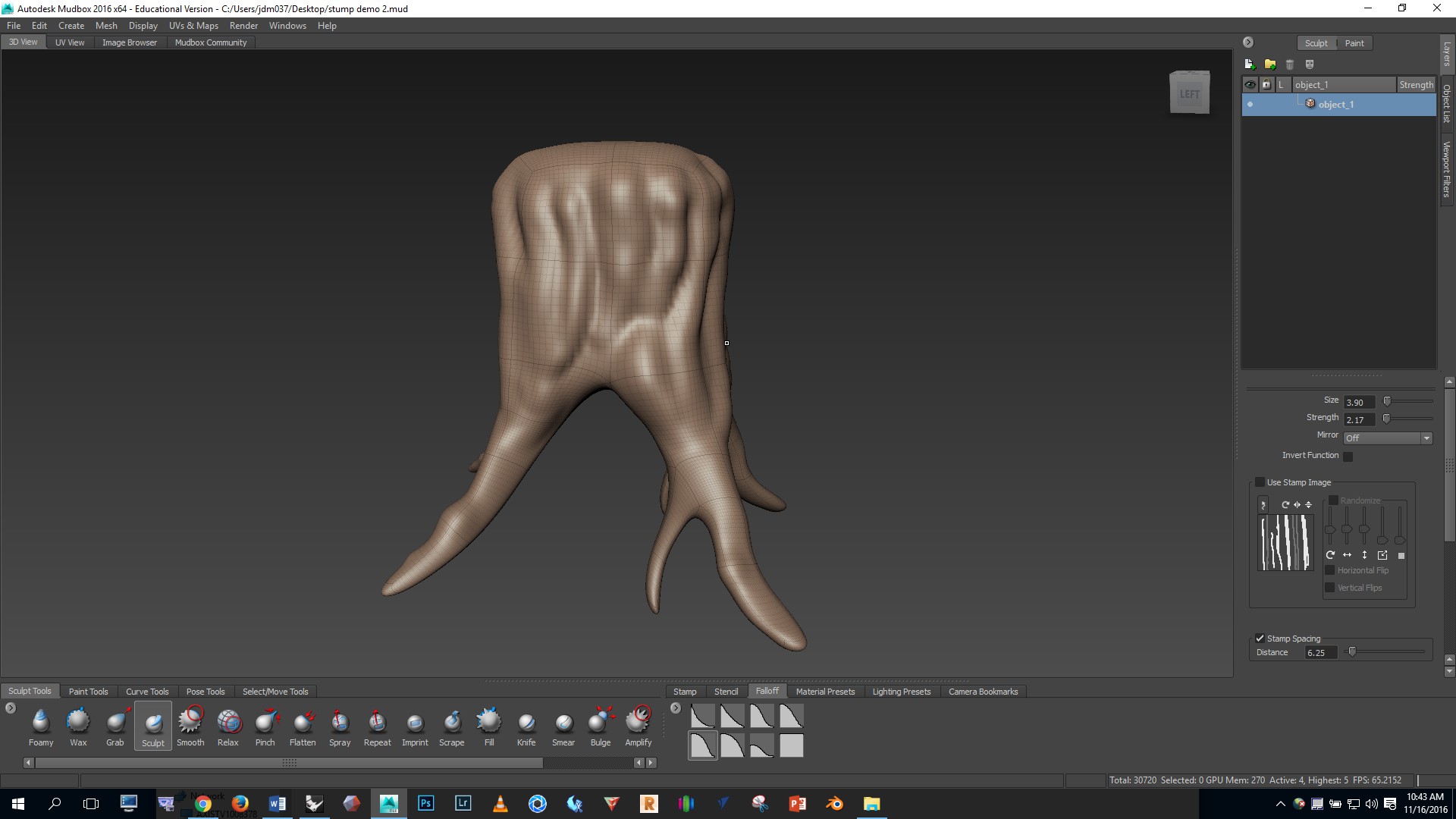
Now let’s use the SCULPT brush to do some sculpting and add detail. If you click on the FALLOFF tab on the lower right you’ll see that we can adjust the type of mark the brush will leave. In this case I found that the #2 option worked best for my purposes.
Notes:
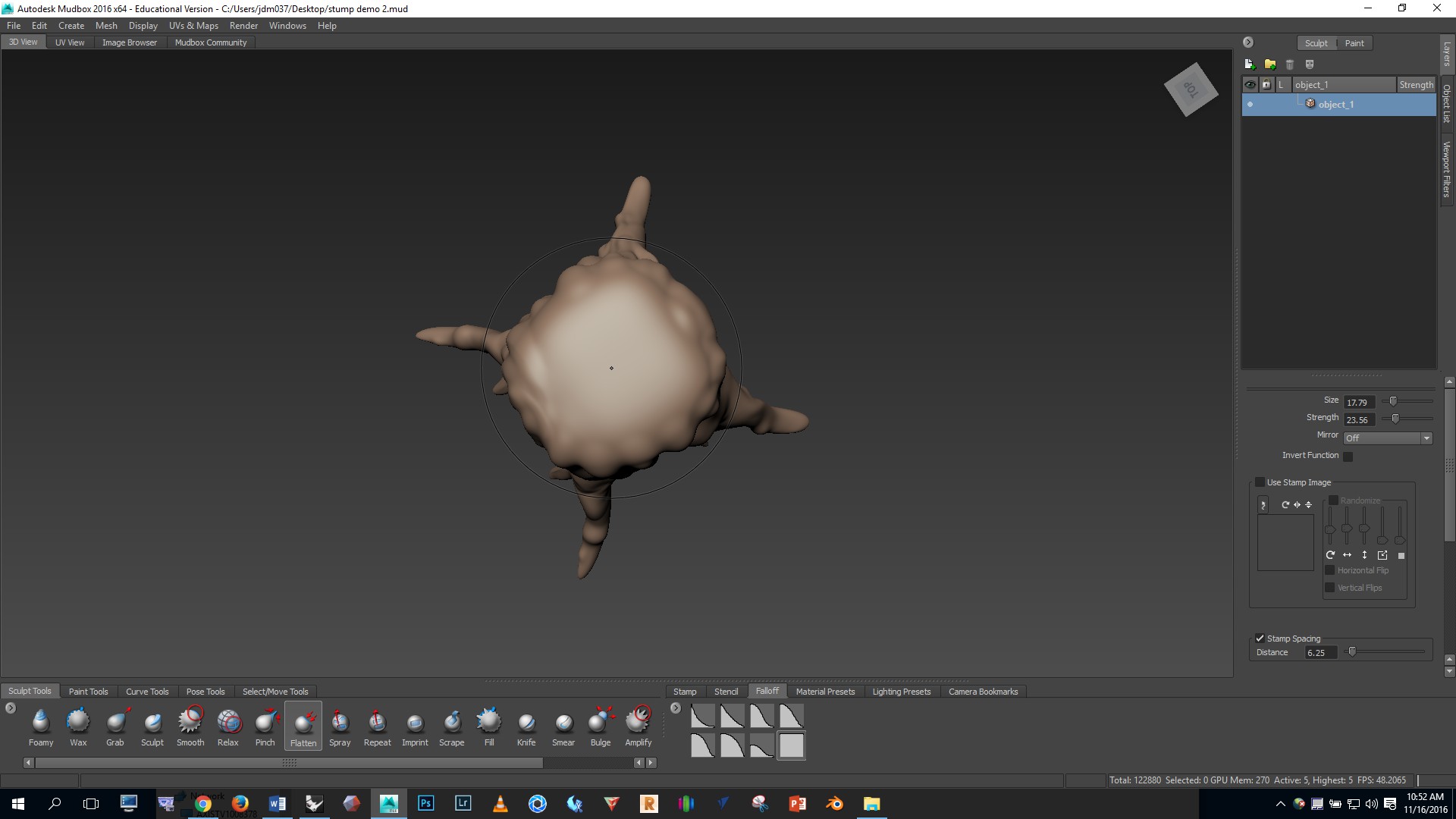
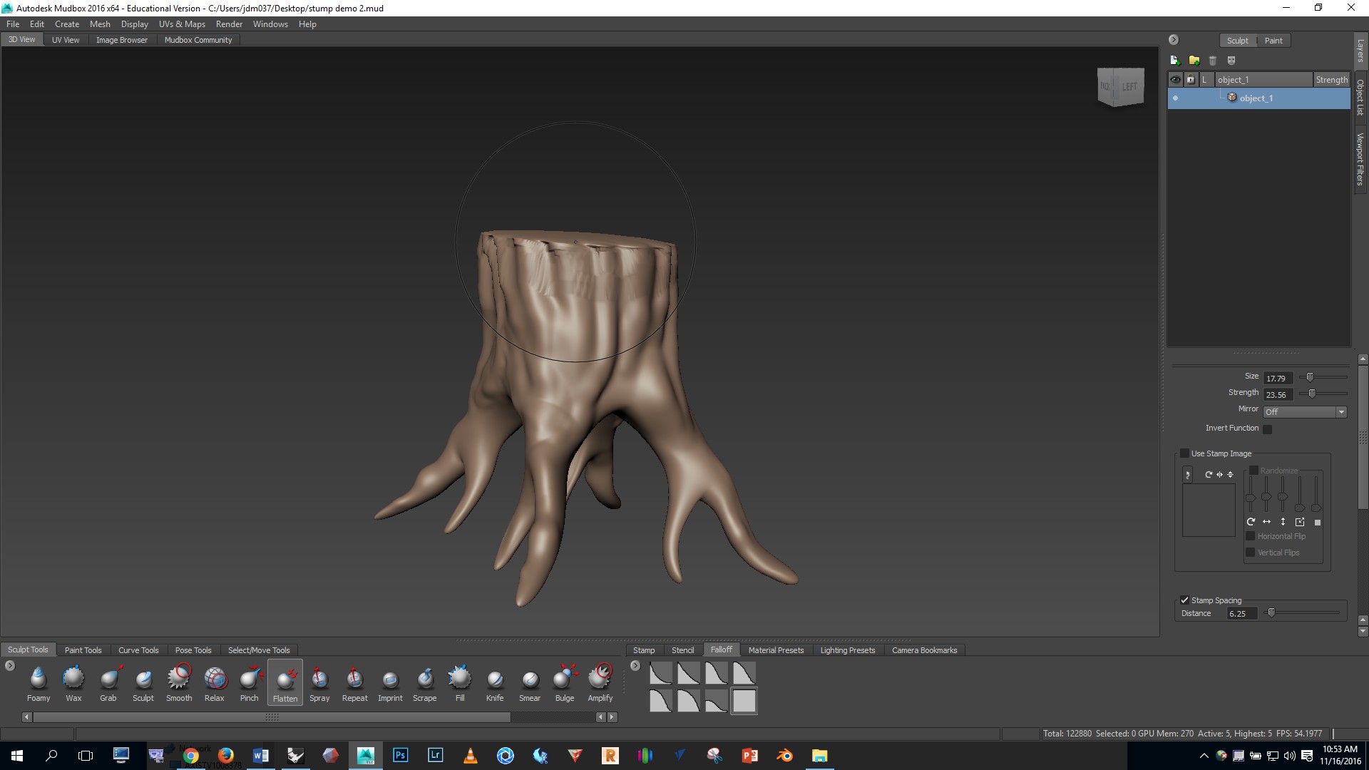
To flatten the top of the stump I selected the FLATTEN brush and used a FALLOFF option 7. Then I orbited so I was looking at the stump from above and smooshed the top down.
You can see that the top edges got a bit messed up. I fixed this by smoothing with the SHIFT key.
The top indents needed to be pushed in. I did this with the SCULPT brush, a sharp #1 FALLOFF, and by holding CTRL to use the INVERTED brush. Then, to make the top edge even sharper I then used the PINCH brush.
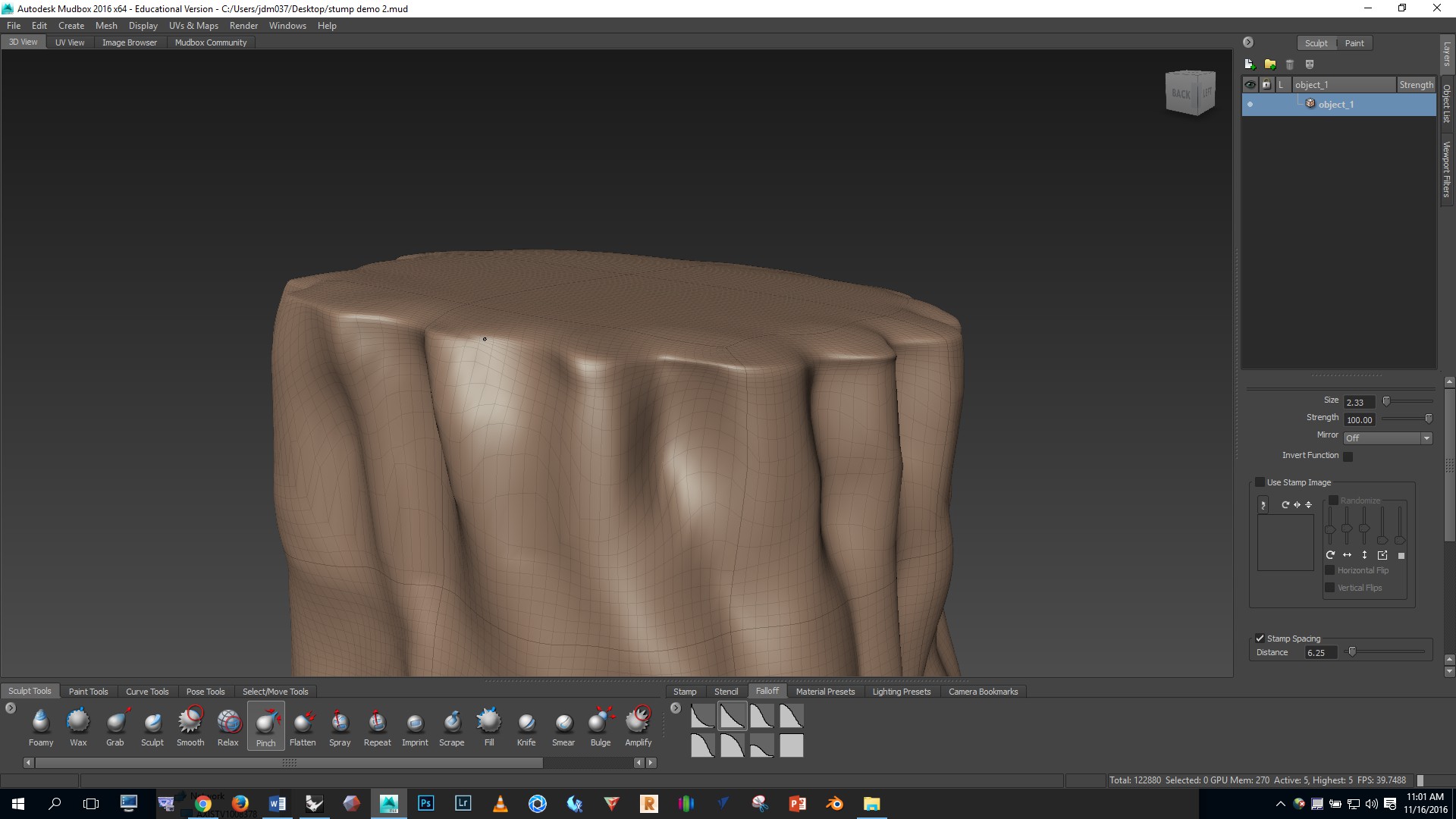
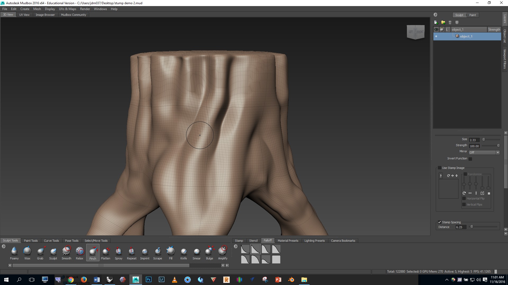
The PINCH brush was also useful for creating sharper creases along the side of the stump.
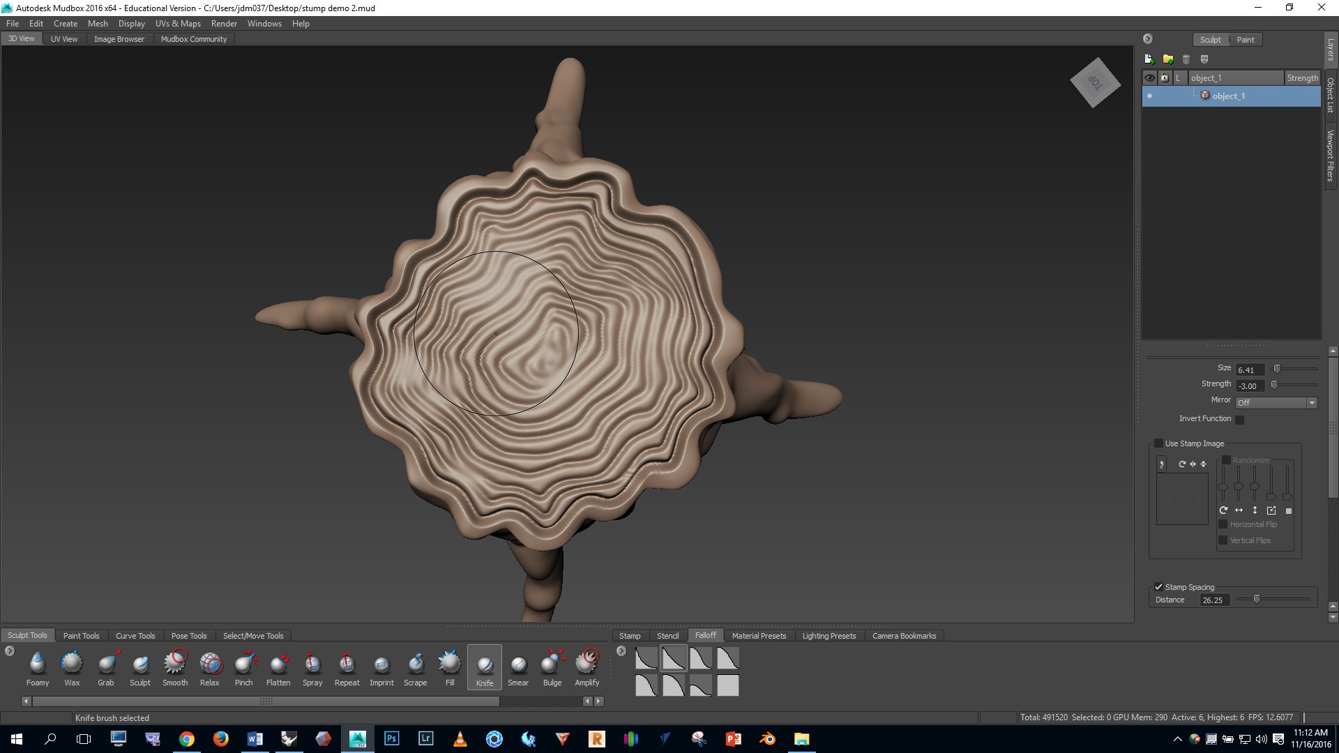
Now let’s add the rings on the top. Add a couple extra levels of subdivision by pressing SHIFT D. Then select the KNIFE brush and use a brush size of .3 and strength of -3. Go to the top view and work from the outside in.
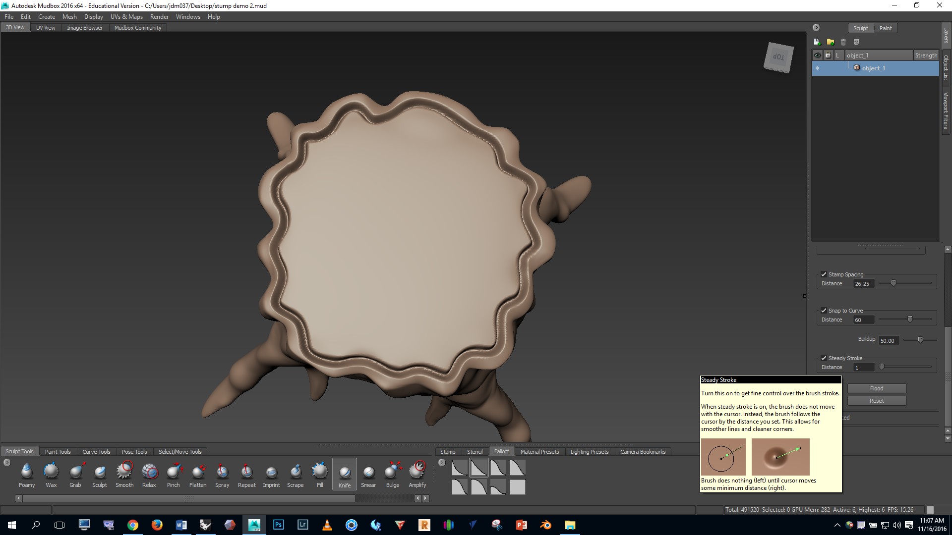
I used the STEADY STROKE brush setting with a distance of 1 (see the settings panel, lower right). Steady stroke helps draw straight lines.
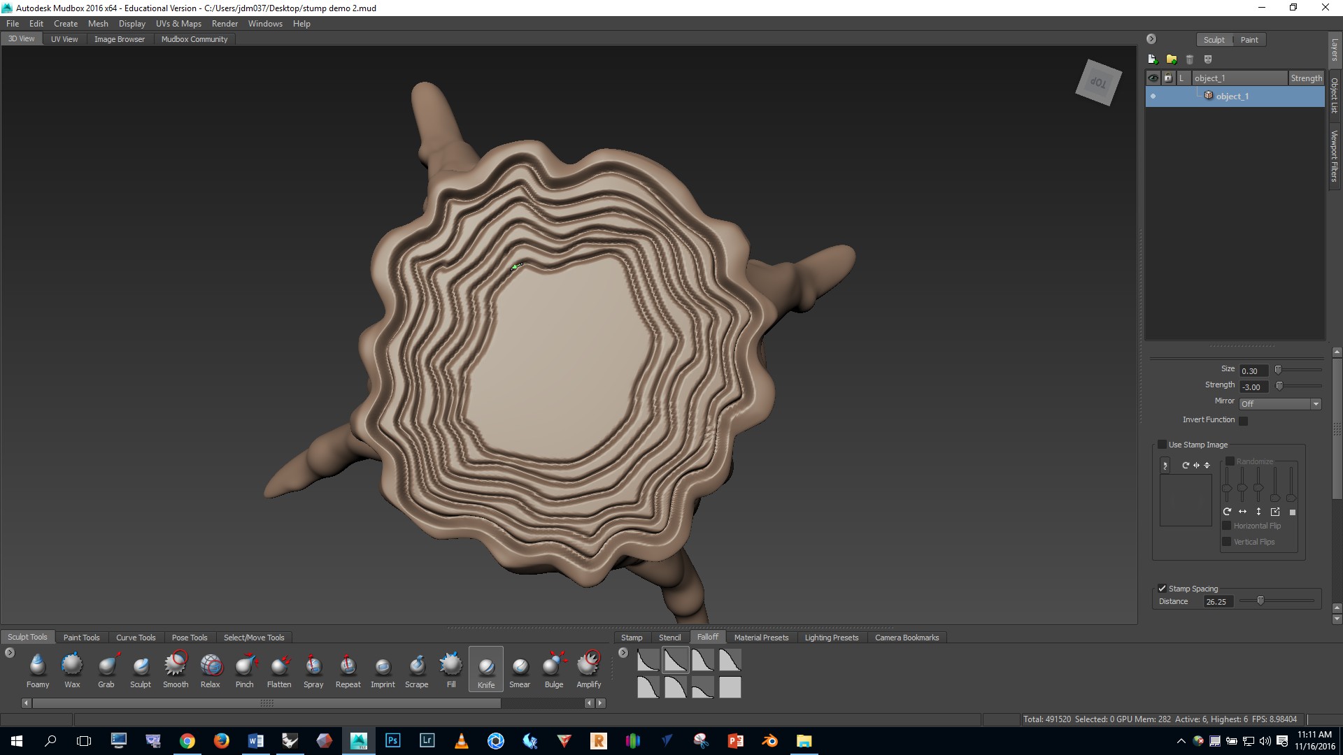
I felt that the regularity of the deep cuts looked unnatural so I smoothed with the SHIFT key.
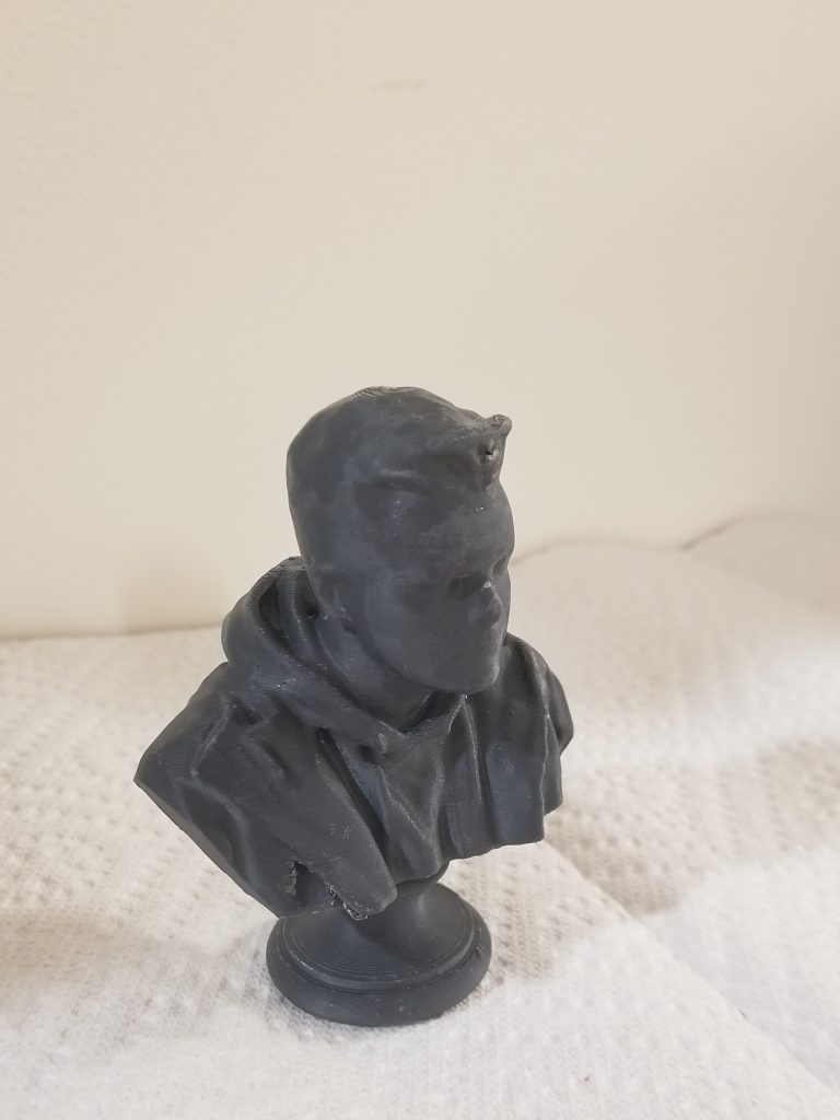
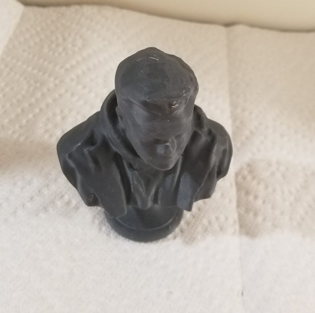
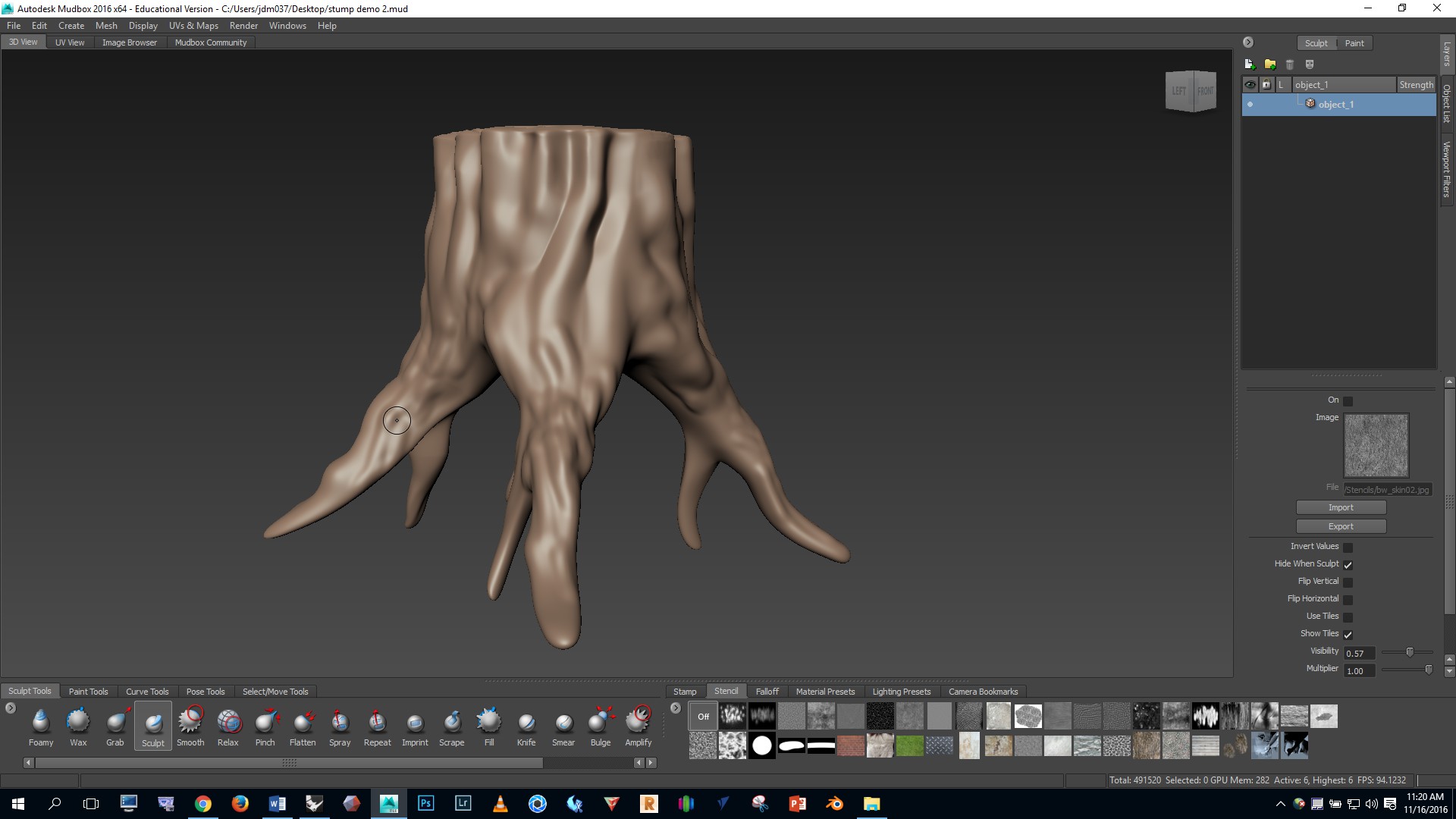
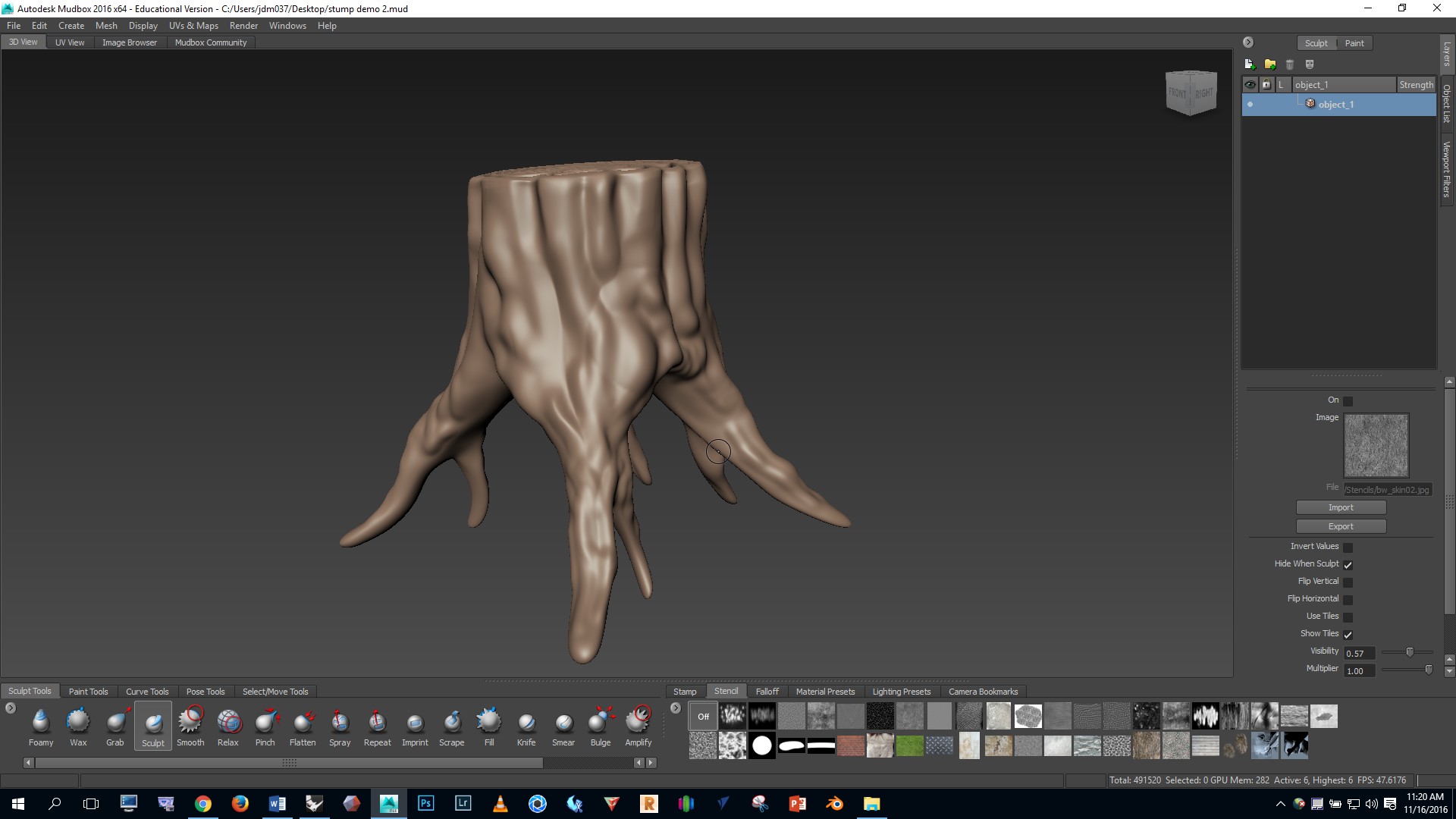
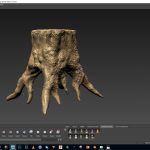
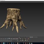
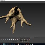
Here are some images of the fully sculpted form.
Now let’s add some bark texture. Click on the STENCIL panel, bottom right and select bw_skin02. PAGE UP to your highest level of subdivision. Notice in Mubox that there are instructions about how to alter the stencil in the lower left corner of the screen.
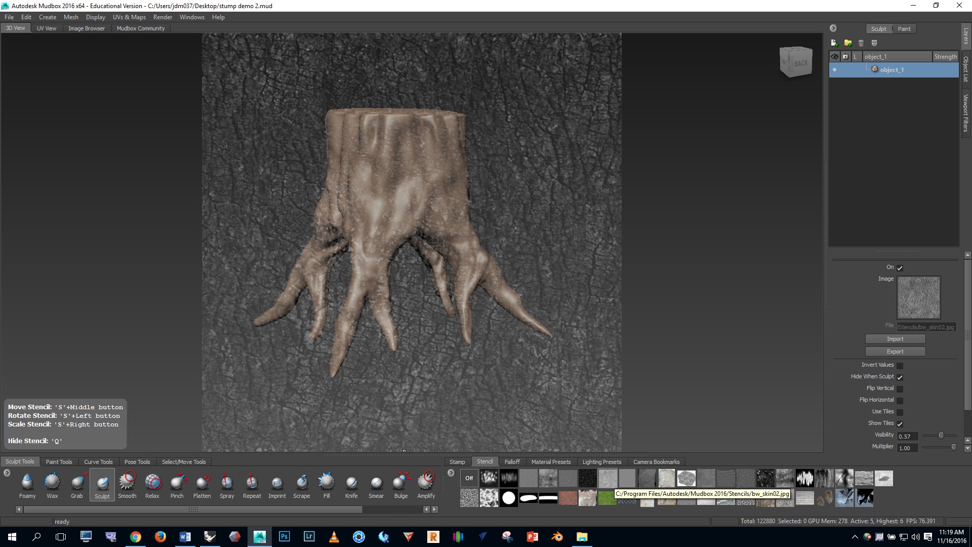
Experiment with using some of the other stencils to create variation in the texture.
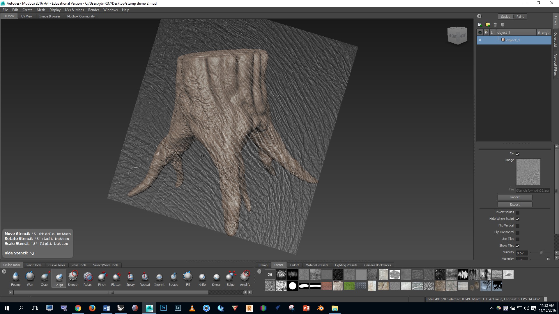
The finished result is shown below. Your stump should be at least as detailed and complex as this example.
To learn more about Mudbox:
A more comprehensive overview of Mudbox is available on Lynda.com. To access these videos, log on to your Lynda.com account using your Bucknell credentials. Then watch these videos.